REMOVAL
w
WARNING:
Always disconnect and
lockout power source before removing any
cover or guard. Do not operate this ma-
chine if any cover or guard is removed.
Remove the following covers and guards to
service the various areas of the machine (Fig-
ure 28, page 39).
Upper enclosure: remove to service cutting
parts.
Feed adapter: remove to access impeller.
Belt cover: remove to access drive belt,
motor pulley and lubricator plumbing lines.
Lubricator cover: remove to service oil mist
lubricator assembly.
Cover plate: remove to access drive belt,
spindle pulley, adapter plate, spindle mounting
fasteners and lubricator plumbing lines.
INSPECTION
Inspect all covers and guards for damage.
Bent or twisted parts will not fit on the machine
properly and may prevent safety switches from
lining up. Straighten parts or replace if neces-
sary.
INSTALLATION
Replace all covers and guards in their prop-
er locations; replace fasteners and tighten se-
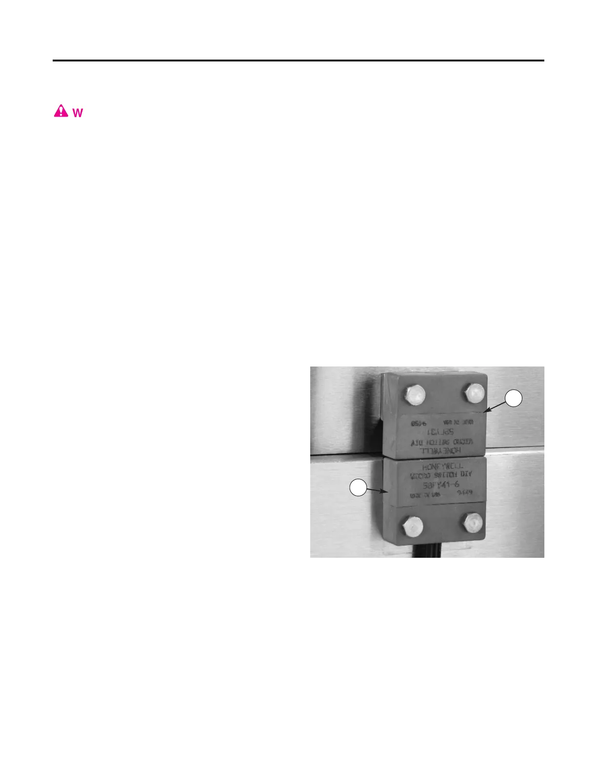
curely. Covers and guards equipped with safe-
ty switches must have actuators within 1/16"
of sensors to complete safety switch circuit
(Figure 27).
MAINTENANCE
Covers and Guards
38
Figure 27 — Safety switch sensors and actuators
must be aligned and within 1/16" (1) Sensor, (2)
Actuator
1
2
 Loading...