A program is available from Urschel Labora-
tories that will allow customers to get up to
eight new blade edges from a single set of mi-
crocut blades (.084" thick blades only).The first
four edges are obtained using standard and
reverse slot blade holding rings. If the microcut
blades can be re-sharpened, a backing ring
for reduced width blades can be installed to
give four additional edges. See chart, page
125.The first four cutting edges are obtained
as follows:
First set of cutting edges: a new set of
blades is installed in the microcut head. Stan-
dard blade holding rings are used (Figure 74).
Second set of cutting edges: each dull
blade is turned over to present all new cutting
edges
Third set of cutting edges: upper and
lower blade holding rings with reverse slots
(“R” suffix in description number, marked on
the ring) replace standard blade holding rings
in the microcut head.Blades are installed so as
to present new cutting edges (Figure 75).
Fourth set of cutting edges: blades are
turned over to present new cutting edges.
Microcut blades must be evaluated at this
point. Blades must be able to be re-sharpened
to a width of .335" (+.0000/-.0005"). Blades that
are severely worn or that have been damaged
by foreign material or from coming in contact
with the impeller generally cannot be re-ground
(Figure 76, page 71). To obtain the most eco-
nomical use, microcut blades should be in-
spected periodically and removed from the
head before they are worn beyond the point
that they can be re-ground. Blades can be re-
ground by a machine shop that uses diamond
faced grinding wheels, or by Urschel Labora-
tories, Inc., see page 71. Using reground
blades, four additional edges are obtained as
follows:
Fifth, sixth, seventh and eighth set of cut-
ting edges: backing ring for reduced width
blades replaces standard backing ring in the
microcut head.The resharpened blades are
used in the microcut head as outlined for the
original four edges.
MAINTENANCE
Microcut Blades
70
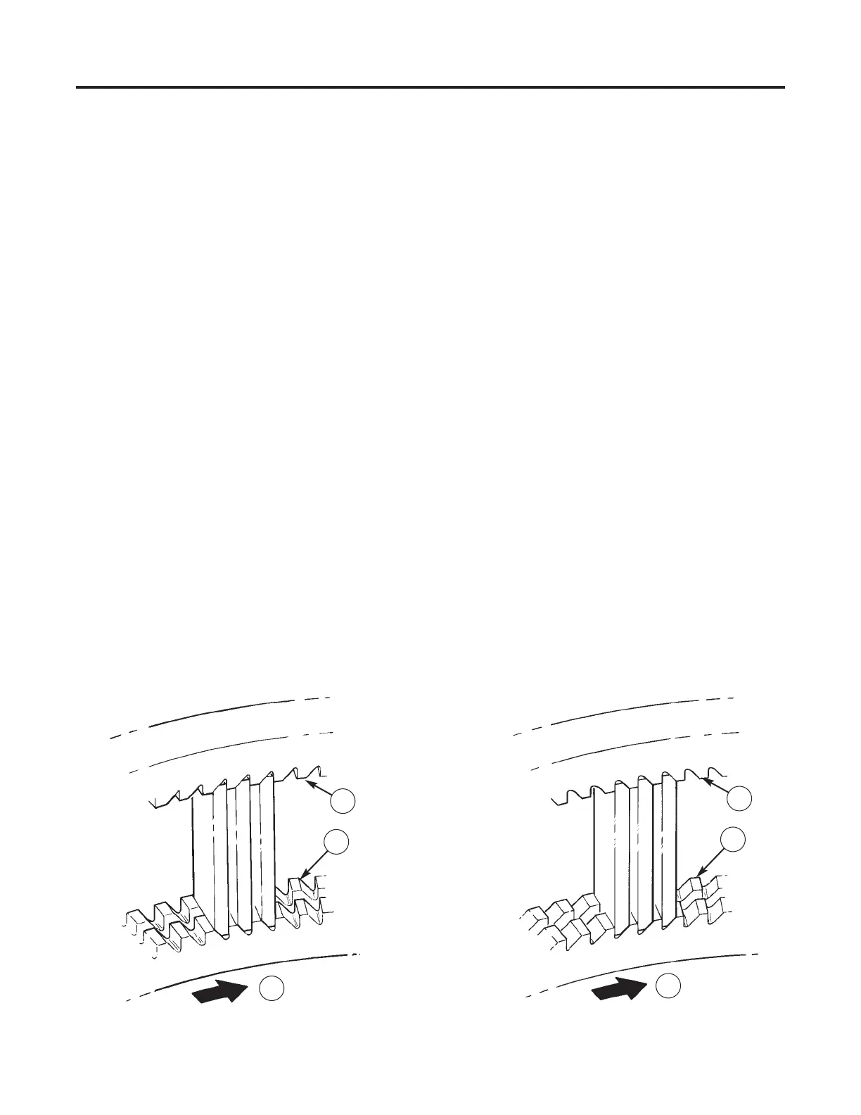
Figure 74 — Standard Blade Orientation. (1) Standard
Blade Holding Ring, (2) Impeller Rotation
Figure 75 — Reverse Blade Orientation. (1) R-Series
Blade Holding Ring (Reverse Slot), (2) Impeller
Rotation
1
1
2
1
1
2