DISASSEMBLY
To change timing belt and/or pulleys, or to
remove spindle pulley prior to spindle removal,
proceed as follows:
1. Disconnect and lock out power source.
Remove feed assembly and reduction
head. See “Disassembly”, pages 44—52.
2. Remove cover plate and belt guard. See
“Covers & Guards”, page 38.
3. Loosen motor mount fasteners and slide
motor toward spindle until timing belt
drops. Remove timing belt.
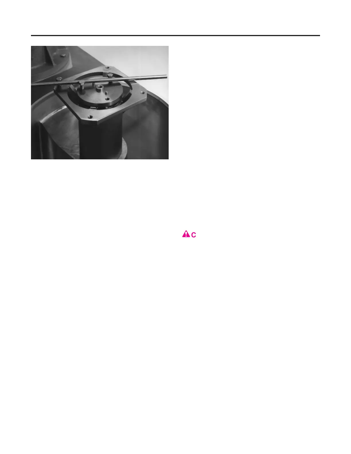
4. Remove spindle pulley. Spindle shaft
must be held stationary to remove spindle
pulley. Insert two 3/8" cap screws into
impeller shaft and one 3/8" cap screw into
spindle flange (Figure 79). Place screw-
driver or bar between screws to prevent
shaft from turning. Remove fastener and
spindle pulley. Motor pulley need not be
removed to change spindle. To remove
motor pulley, engage motor brake (Figure
34, page 46) and remove fastener.
NOTE:
A pulley puller is available if pulleys
prove difficult to remove. Remove flange on
spindle pulley and retainer on motor pulley to
attach puller. See “Tools”, page 82.
At this point drive parts can be inspected or
changed. See “Drive Chart”, page 141, for
appropriate pulleys and timing belt to obtain
desired operating speed. If spindle is to be
removed, see “Removal”, page 54.
w
CAUTION:
Operate machine at recom-
mended speeds only! Operating at other
than recommended speeds could create a
safety hazard and cause excessive wear or
damage to machine parts.
INSPECTION
Timing belt: Belt is reinforced with steel
cables and is almost free from stretch. Inspect
for wear. If timing belt fails during operation,
the steel cables may have separated from belt
and wrapped around impeller shaft above
spindle pulley. If this occurs, check shaft and
seal for damage. The lower bearings in the
spindle assembly should also be inspected for
contamination.
Pulleys and shafts: Remove any nicks or
burrs. Make sure pulley flanges are securely
attached.
MAINTENANCE
Drive Parts
74
Figure 79 — Method to prevent spindle shaft from turn-
ing while removing spindle pulley