Refer to Figure 20 and proceed as follows:
DISASSEMBLY
1. Disconnect and lock out power
source. After machine has come to a
complete stop, press the “I” (START)
button to verify machine will not start.
Remove four (4) hand knobs on front
cover with feed hopper and remove the
cover with hopper.
2. Remove feed adapter. Remove four (4)
hex nuts and clamp screws. Lift adapter
evenly by using a slight rocking motion.
Handle adapter carefully to avoid damag-
ing machined surfaces.
3. Remove cutting head. Four (4) screws
hold cutting head in place. Lift carefully
over impeller and remove from machine.
4. Remove impeller hex nut, washer and
impeller.
CAUTION: The impeller hex nut
is self-locking using a plastic insert. It
will deform with use and the locking
effect will be lost. If the nut can be
turned with finger pressure, it must be
replaced. The loss of this nut due to
insufficient tightening or from vibra-
tion while machine is running can
result in damage to the machine.
36
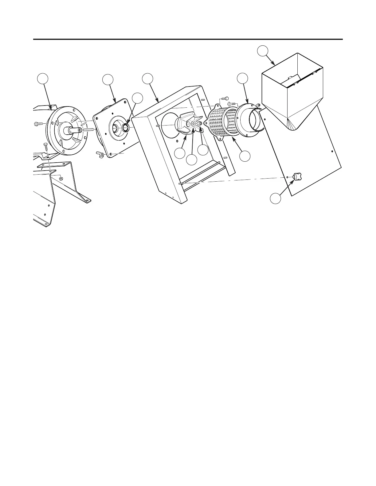
MAINTENANCE
Feed Assembly & Cutting Heads
Figure 20 — Feed assembly. (1) Motor, (2) Cutting Head Holder, (3) Seal, (4) Cutting Enclosure, (5) Impeller,
(6) Impeller Washer, (7) Hex Nut, (8) Cutting Head, (9) Feed Adapter, (10) Front Cover with Feed Hopper,
(11) Hand Knob
1
2
4
3
5
6
7
8
10
11
9