INSPECTION
All parts should be cleaned, inspected for
serviceability and repaired or replaced if
necessary.
Feed adapter: Inspect for damage and
wear. Make sure all mating surfaces are
clean and free from nicks and burrs.
Cutting head: Inspect for damage and
wear. Make sure all mating surfaces are
clean and free from nicks and burrs.
Urschalloy and fabricated heads can be
resharpened. See “Resharpening Cutting
Heads”, pages 38–39. Replace cutting heads
when damaged or when quality of cut product
is no longer satisfactory.
Impeller: Clean and inspect for damage
or wear. When impeller inserts become worn
(rounded on leading edge), impeller should
be replaced or returned to the factory for re-
tipping. If impeller is worn excessively and
insert seats are damaged, impeller must be
replaced. Make sure all mating surfaces are
clean and free from nicks and burrs.
Seal on cutting head holder: Inspect
for hardening or cracking. Replace if neces-
sary by removing cutting enclosure and cut-
ting head holder. Four (4) wing nuts hold
enclosure to the cutting head. Install with lip
facing out (towards impeller).
REASSEMBLY
1. Install impeller with washer and hex
nut, using a new hex nut if necessary.
Mating surfaces must be clean and free
of nicks and burrs. Tighten securely.
2. Install cutting head. Mating surfaces
must be clean and free of nicks and burrs.
Cutting head must be properly seated.
Replace screws and tighten securely.
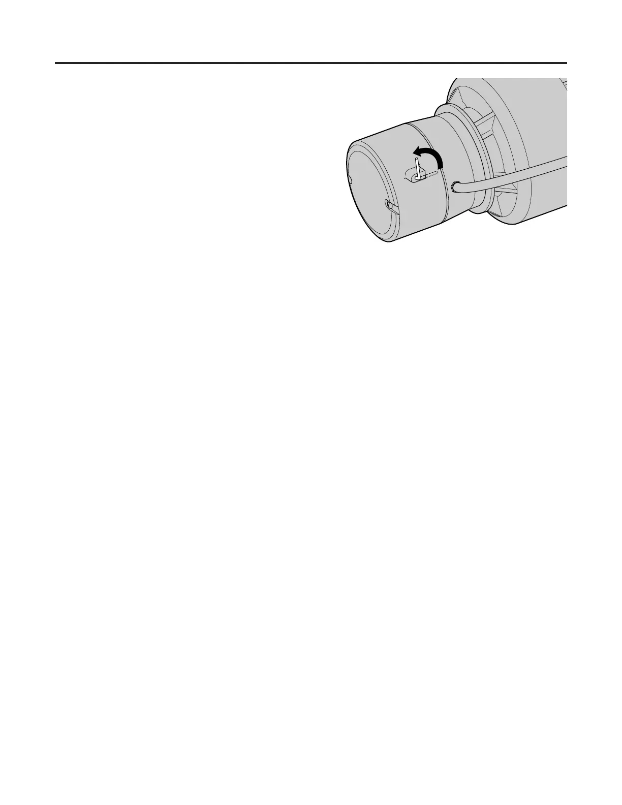
Release motor brake (Figure 21) and
rotate impeller backwards (counterclock-
wise) several times by hand to make cer-
tain there is no metal to metal contact.
WARNING: Keep fingers away from
cutting head! Do not pinch fingers between
cutting head and impeller. Cutting edges
are sharp and could cause personal injury.
3. Install feed adapter. Mating surfaces
must be clean and free of nicks and burrs.
Replace clamp screws and hex nuts.
Tighten securely.
4. Install front cover with feed hopper.
Align safety switch sensor and actuator
on enclosure (see “Installation”, page 32).
Secure with the four (4) hand knobs.
MAINTENANCE
Feed Assembly & Cutting Heads
37
Figure 21 — Release motor brake