INSPECTION
WARNING: In the event of an elec-
trical problem, only a qualified electri-
cian should inspect or repair the fault.
Voltages dangerous to life exist in the
starter enclosure! The power discon-
nect/ lockout switch must be in the “O”
(OFF) position. Live voltages are still
present in the box even though power
disconnect/lockout switch is off. Always
disconnect and lock out power source
to starter enclosure before beginning
electrical inspection or repair.
The electrical assembly must be in good
working condition before operating this
machine. For a description of amplifier and
safety switch operation and method for
checking this system, see pages 12–15.
Electrical schematics are located in the
starter enclosure and on pages 66–67.
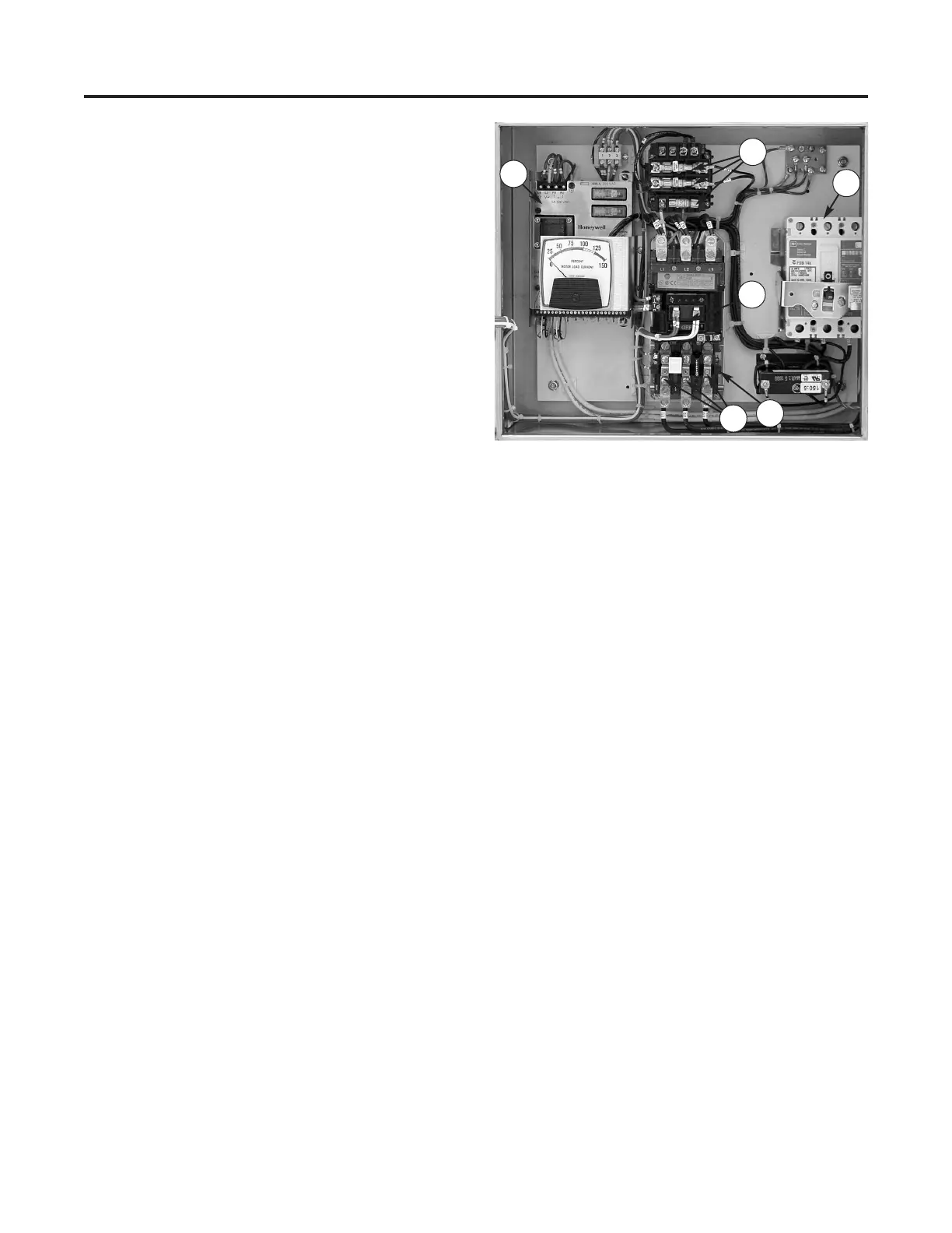
Refer to Figure 23; inspect the following:
Starter enclosure: Inspect interior of
starter enclosure for corrosion. If a signifi-
cant amount of water accumulates in the
bottom of the starter enclosure, check the
breather drain. Breather drain should be
free from obstruction. Excess water could
also indicate an opening or loose fitting that
allows water to enter the enclosure. Check
all access points to the enclosure. Check
gasket around door and window. Inspect
“O” (STOP) and “I” (START) push button
assemblies, selector switches and pilot light
assembly for damage or corrosion. Replace
rubber boots and pilot light lens if damaged.
NOTE: Electrical components that fail
due to water or chemical contamination
are not covered under the warranty.
MAINTENANCE
Electrical Assembly
40
1
2
5
3
6
4
Figure 23 — Typical starter enclosure interior,
NEMA* (CE compliant enclosure not shown.).
(1) Circuit Breaker, (2) Starter Coil, (3) Heaters,
(4) Amplifier, (5) Transformer Fuses, (6) Overload
Relay
*National Electrical Manufacturers Association