EasyManua.ls Logo

Urschel COMITROL 1700 - Page 17

Default Icon
233 pages
Print Icon
To Next Page IconTo Next Page
To Previous Page IconTo Previous Page
Loading...
15
SAFETY
Safety Switch System
RELAY
CONDITION
C
2
LOGIC AMPLIFIER
FYQLA1-140R-3
D
E
S
O
L
N
E
P
O
117 V
6
OBWR
5
OBWR
4
OBWR
3
OBWROBWRO
R2R1L2L1
RW B
1
3
6
7
5
4
1
2
9
8
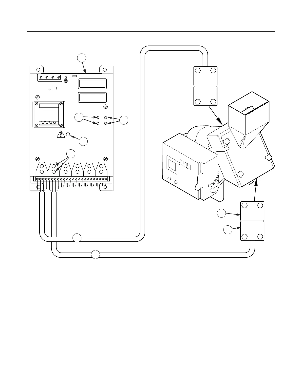
Figure 11 — Amplifier and safety switches with corresponding covers and guards. (1) Cutting Enclosure,
(2) Front Cover with Feed Hopper, (3) Amplifier, (4) Green “Relay Condition” LEDs, (5) Red “Relay Condi-
tion” LEDs, (6) Red “Attention” LED, (7) Red “Switch Output” LEDs, (8) Sensor, (9) Actuator

Table of Contents

Related product manuals