X5 AC Drive User’s Manual Chapter 4: Connections
DPD00089A - 43 - © 2009 Vacon Incorporated All Rights Reserved
4.6.5 Modbus Connection Diagram
Figure 4-9: RS-485 Connector (Modbus) Pinout
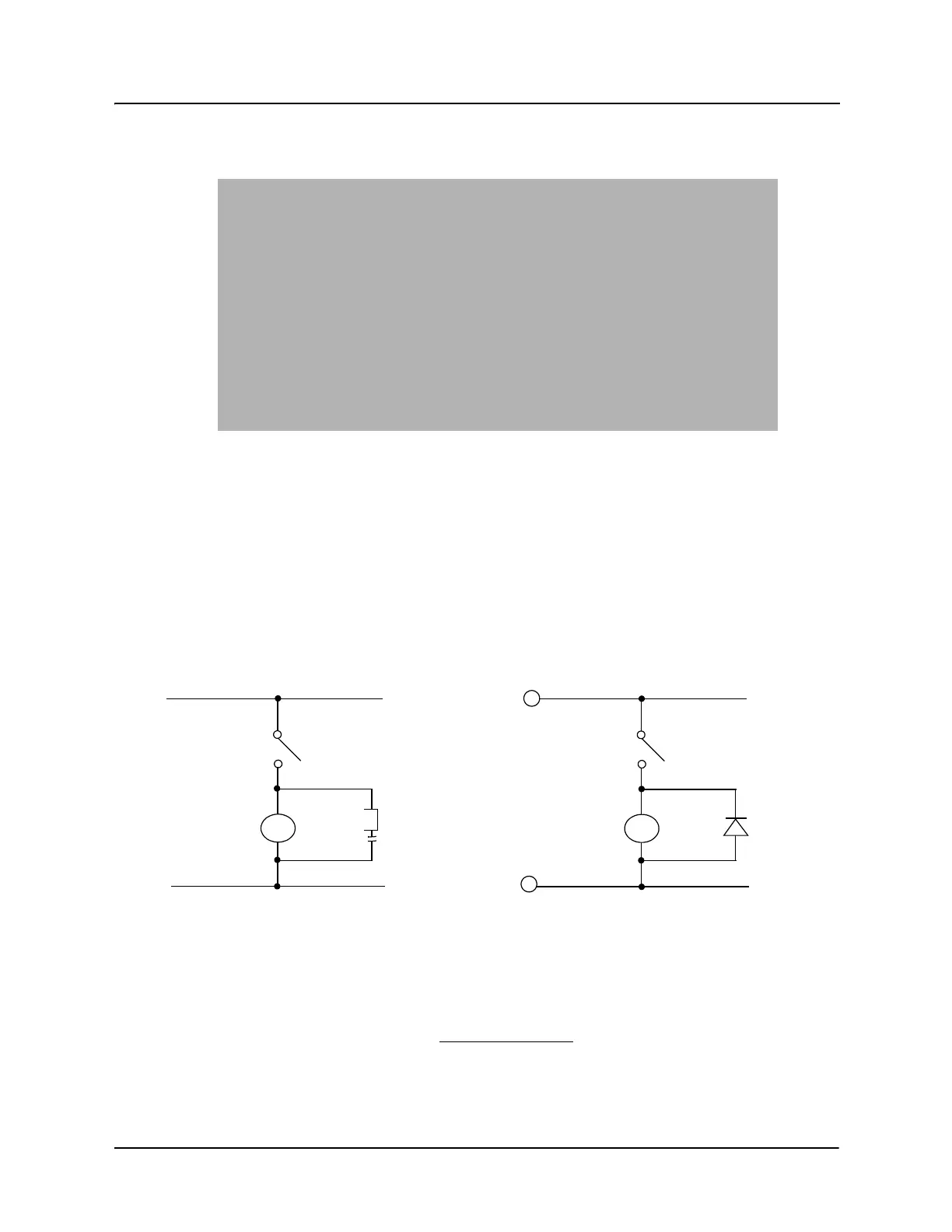
4.7 Reducing Current Surges and Voltage Transients
Inrush currents to coils of magnetic contactors, relays, and solenoids associated with or near the
drive can induce high current spikes in the power and control wiring, causing faulty operation. If this
occurs, a snubber network consisting of a series resistor and capacitor for AC loads, or a free-
wheeling or flyback diode for DC loads, can be placed across the relay coil to prevent this condition.
The following component values should be used for 115 VAC or 230 VAC relays or solenoids.
Figure 4-10: Connection Diagram for AC and DC Relay Coils and Solenoids
For magnetic contactors, relays, and solenoids energized from a DC source, use a free-wheeling
diode of the high-speed, fast-recovery type. Connect the diode across the coil as shown in Figure 4-
10. The diode current and voltage should be selected using the following formulae:
For Main Circuit Contactors and Solenoids
C = 0.2 MFD, 500 VDC R = 500 5 Watts
For Auxiliary Control Circuit Relays
C = 0.1 MFD, 500 VDC R = 200 2 Watts
RC Type
Snubber
AC
Coil
Coil
DC
+
-
Freewheeling
Diode
Diode Current Rating (A)
Coil Capacity (VA)
Rated Voltage of Coil (V)
Rated Voltage of Coil (V) x 2
Diode Voltage Rating