X5 AC Drive User’s Manual Chapter 3: Receiving and Installation
DPD00089A - 26 - © 2009 Vacon Incorporated All Rights Reserved
3.4 Cover Assembly and Torque Specifications
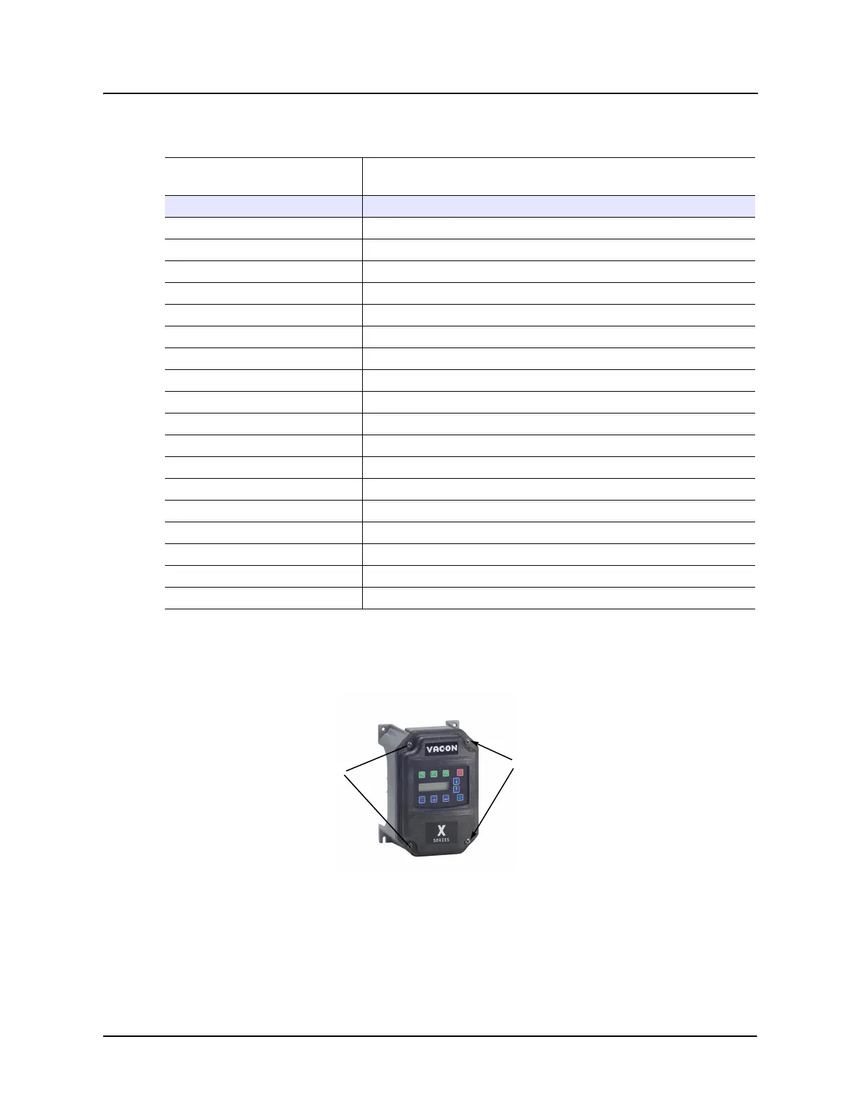
Figure 3-1 shows the locations of the X5 cover screws. The torque range for the X Series Size 1
cover is 18-26 in/lbs.
Figure 3-1: X5 Cover Assembly and Screw Locations
Torque specifications for control terminals and power terminals are listed in “General Wiring
Information” on page 29 .
X5C42000D 2302
X5C50010C 32
X5C50020C 50
X5C50030C 66
X5C50050C 112
X5C50075C 159
X5C50100C 187
X5C50150C 334
X5C50200C 431
X5C50250C 528
X5C50300C 597
X5C50400C 742
X5C50500C 877
X5C50600C 766
X5C50750C 913
X5C51000C 1542
X5C51250D 1988
X5C51500D 2282
X5C52000D 3043
Table 3-1: Dissipation Requirements for X5 Models in Enclosures (Page 2 of 2)
Model
Required Dissipation for Models Entirely Inside an Enclosure at
Rated Current, 3KHz Carrier Frequency (Watts)
Cover screw locations
Cover screw locations