Chapter 5 _________________________________________________________ Theory of Operation
VAISALA _______________________________________________________________________ 105
0201-074
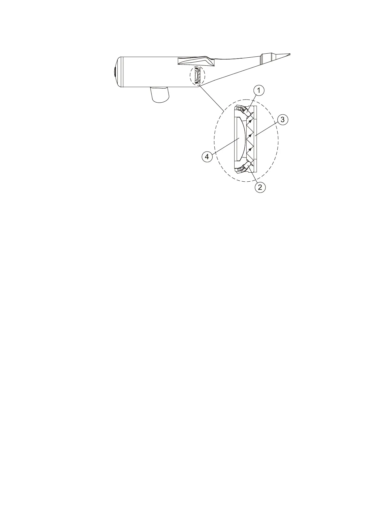
Figure 37 Window Contamination Measurement Principle inside
Transmitter and Receiver FSM102
The following numbers refer to Figure 37 above:
The main transmitter LED temperature is controlled by a control circuit
that includes a temperature sensor and a heating element. In cold
environments the heating circuitry warms up the LED to its proper
operating temperature to keep the LED emission cone and wavelength
stable.
Receiver Unit FSR102
The Receiver unit consists of a light receiver detector, a low-noise
preamplifier, high pass (HP) and band pass (BP) filters, two A/D
converters, a backscatter measurement light source LED, window
contamination measurement circuitry, and some control and timing
electronics.
The receiving PIN photodiode senses the transmitted light pulses
scattered from the aerosol particles. The signal voltage is filtered and
detected by the phase sensitive lock-in amplifier that is synchronized
with the transmitter.

 Loading...


