Chapter 3 ________________________________________________________________ Installation
VAISALA ________________________________________________________________________ 51
1303-063
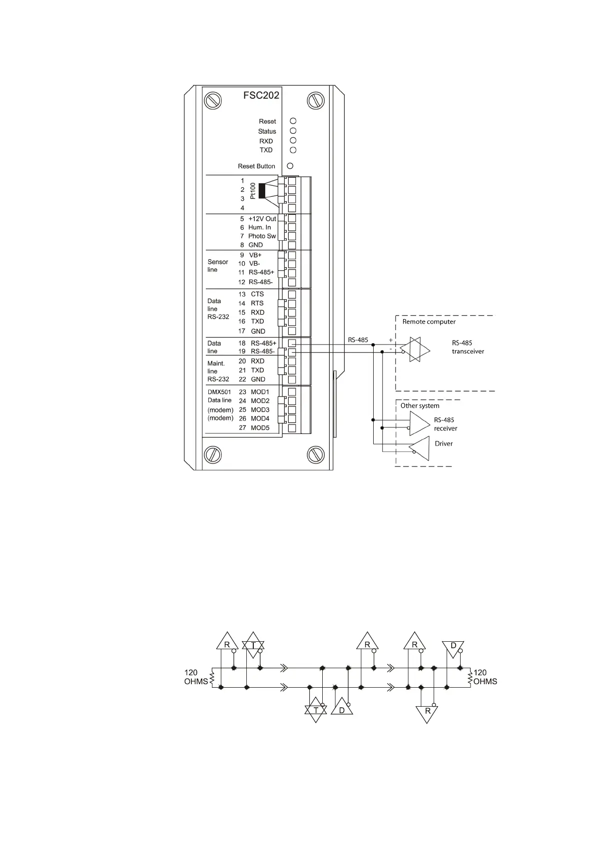
Figure 27 RS-485 Communication Option
Terminate the RS-485 chain with a 120 Ω resistor. This is especially
important with long cables. If the FS11 sensor is at the end of the RS-485
chain, the 120 Ω resistor can be connected across the screw terminal
pins. The 120 Ω resistor is available in a plastic bag attached to the
power cable inside the interface unit's enclosure.
Figure 28 below illustrates an RS-485 application using a half-duplex
data transfer over a single twisted pair.
9502-061
Figure 28 RS-485 Application