Chapter 2 _______________________________________________ Introduction and Specifications
VAISALA_______________________________________________________________________ 29
occur in high reflectivity gradients. The 16-bit I and Q resolution is passed
to the RVP902 server for both H and V.
One of the primary advantages of the digital receiver approach is that wide
linear dynamic range can be achieved without the need for complex AGC
circuits that require both phase and amplitude calibration.
0916-010
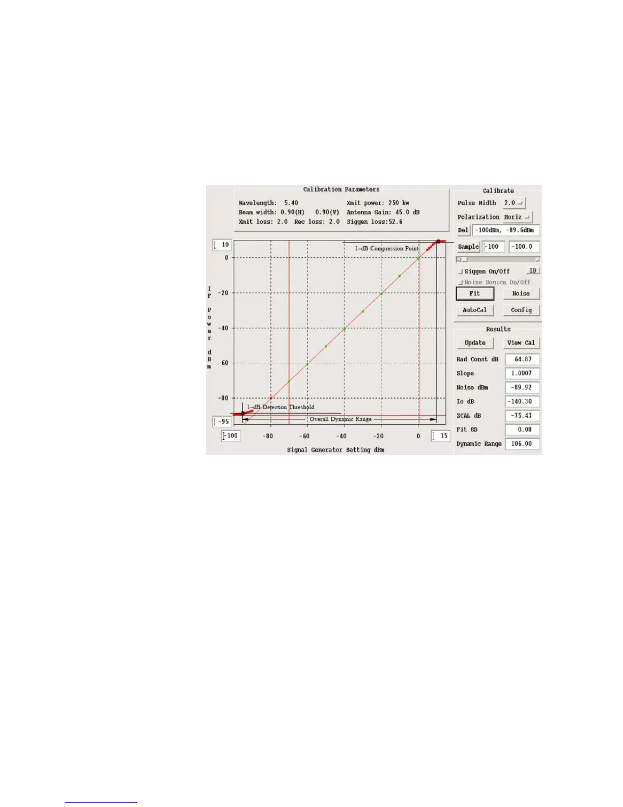
Figure 6 Calibration Plot for RVP901
Figure 6 shows a calibration plot for a 16-bit IFDR with the digital filter
matched to a 2 microseconds pulse. The performance in this case is
>105 dB dynamic range.
The RVP900 performs several real-time signal corrections to the I/Q
samples from the Rx, including:
- Amplitude Correction—A running average of the transmit pulse
power in the magnetron burst channel is computed in real-time by the
RVP900. The individual received I/Q samples are corrected for
pulse-to-pulse deviations from this average. This can substantially
improve the “phase stability” of a magnetron system to improve the
clutter cancelation performance to near Klystron levels.
- Phase Correction—The phase of the transmit waveform is measured
for each pulse (either the burst pulse for magnetron systems or the Tx
Waveform for coherent systems). The I/Q values are adjusted for the
 Loading...