USER’S MANUAL__________________________________________________________________
94 __________________________________________________________________ M211322EN-D
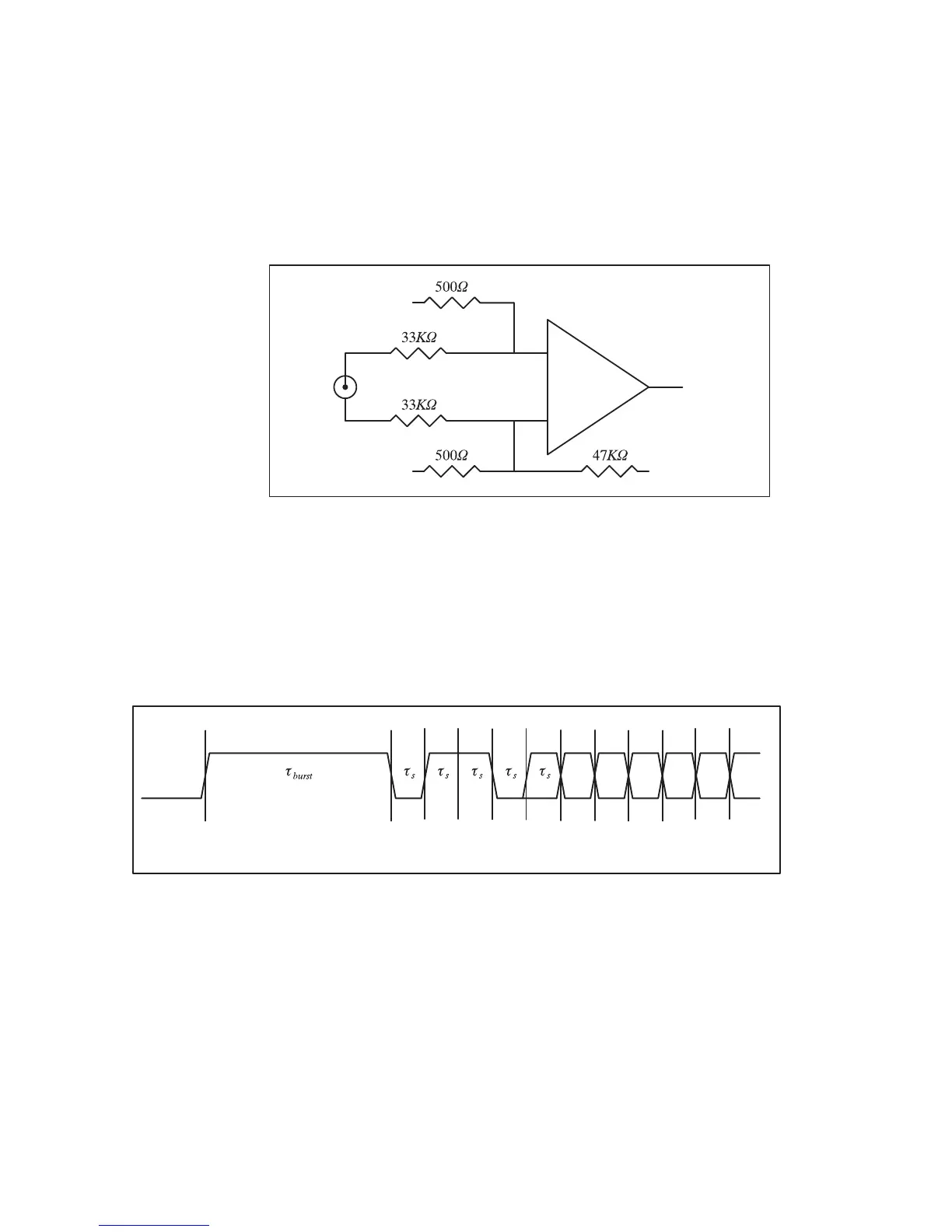
shield and the center conductor of the coax uplink feed the comparator
through 33KΩ isolation resistors; no direct ground attachment is made to
the shield. The 500Ω resistors provide the local ground reference, and the
47KΩ resistor supplies a bias to shift the unipolar uplink signal into a
bipolar range for the comparator.
0916-034
Figure 23 Recommended Receiving Circuit for the Coax Uplink
The uplink signal, shown in Figure 24 on page 92, is periodic at the radar
pulse repetition frequency, and conveys two distinct types of information
to the IFDR. The signal is normally low most of the time (to minimize
driver and termination power), but begins a transition sequence at the
beginning of each transmitted pulse.
0916-035
Figure 24 Timing Diagram of the IFD Coax Uplink
The first part of each pulse sequence is a variable length "burst window",
which is centered on the transmitted pulse and has a duration τ
burst
approximately 800 nanoseconds greater than the length of the current FIR
matched filter. The burst window defines the interval of time during which
the IFDR transmits digitized burst pulse samples, rather than digitized IF
samples, on its downlink. The exact placement and width of the burst
window depends on the trigger timing and digital filter specifications that
 Loading...