2.8 Thermal overload protection T>
(49)
VAMP 24h support phone +358 (0)20 753 3264
Ambient temperature factor (Permitted current due
to tamb). See Figure 2.8-1
The rated current (I
n
or I
mot
)
Cooling time coefficient (cooling time constant =
Time constant for cooling situation
If the transformer's fan is stopped, the cooling will be slower
than with an active fan. Therefore there is a coefficient c for
thermal constant available to be used as cooling time constant,
when current is less than 0.3xI
n
.
Heat capacitance, service factor and ambient temperature
The trip level is determined by the maximum allowed
continuous current I
max
corresponding to the 100 %
temperature rise
TRIP
i.e. the heat capacitance of the
transformer. I
max
depends of the given service factor k and
ambient temperature
AMB
and settings I
max40
and I
max70
according the following equation.
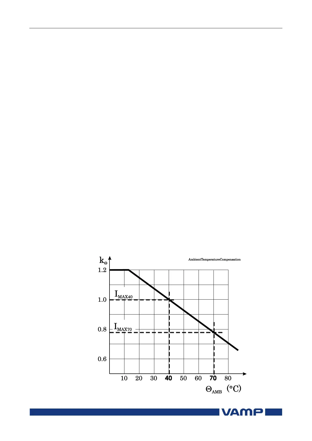
The value of ambient temperature compensation factor k
depends on the ambient temperature
AMB
and settings I
max40
and I
max70
. See Figure 2.8-1. Ambient temperature is not in use
when k = 1. This is true when
I
max40
is 1.0
Samb is “n/a” (no ambient temperature sensor)
TAMB is +40 °C.
Figure 2.8-1 Ambient temperature correction of the overload stage T>.