2.8 Thermal overload protection T>
(49)
VAMP 24h support phone +358 (0)20 753 3264
Example of a behaviour of the thermal model
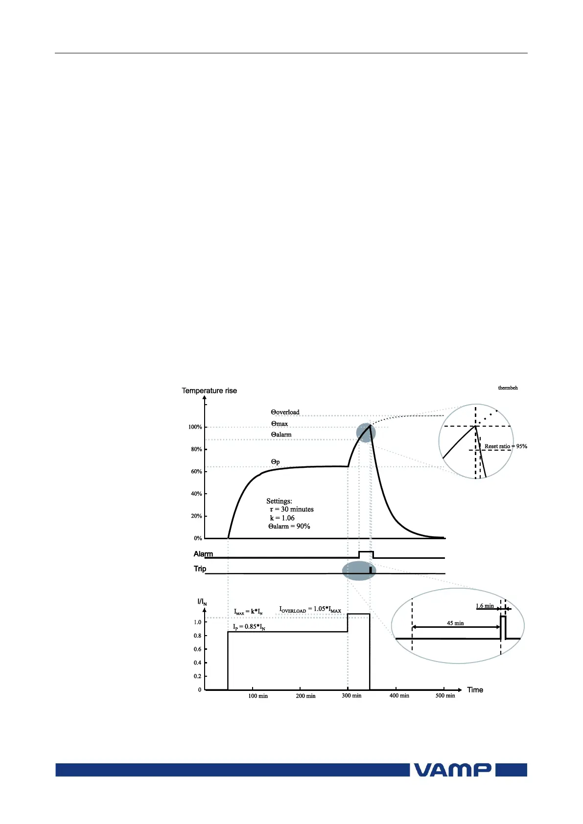
Figure 2.8-1 shows an example of the thermal model behaviour.
In this example = 30 minutes, k = 1.06 and k = 1 and the
current has been zero for a long time and thus the initial
temperature rise is 0 %. At time = 50 minutes the current
changes to 0.85xI
N
and the temperature rise starts to approach
value (0.85/1.06)
2
= 64 % according the time constant. At
time=300 min, the temperature is about stable, and the current
increases to 5 % over the maximum defined by the rated
current and the service factor k. The temperature rise starts to
approach value 110 %. At about 340 minutes the temperature
rise is 100 % and a trip follows.
Initial temperature rise after restart
When the relay is switched on, an initial temperature rise of
70 % is used. Depending of the actual current, the calculated
temperature rise then starts to approach the final value.
Alarm function
The thermal overload stage is provided with a separately
settable alarm function. When the alarm limit is reached the
stage activates its start signal.
Figure 2.8-1. Example of the thermal model behaviour.