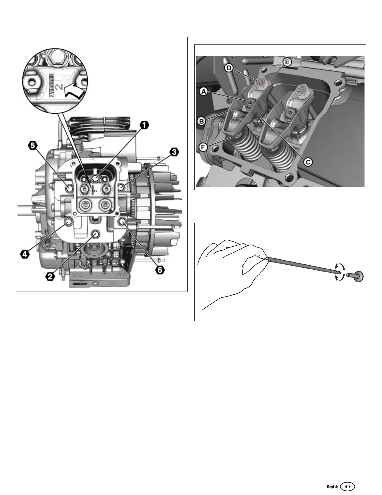
6. Tighten cylinder head bolts in sequence as shown in
Figure 164:
164
A. Tighten bolts to 116lb-in (13.1 Nm) using the
sequence shown.
B. Tighten bolts to 232lb-in (26.2 Nm) using the
sequence shown.
C. Final tighten bolts to 348 lb-in (39.3 Nm) using the
sequence shown.
NOTE: Failure to step-torque cylinder head bolts in the
proper sequence may result in gasket leaks or cause the
cylinder head to warp.
7. Start fasteners (A, Figure 165) to fasten rocker
arms(B)and fulcrums (C) to cylinder head. Tighten
fasteners to 105 lb-in (11.9 Nm).
165
8. Insert push rods into cylinder head bores to engage valve
tappets. Rotate push rods to be sure that ball ends are
seated in valve tappet sockets as shown in Figure 166.
166
9. Install adjuster screws(D, Figure 165)and lock
nuts(E)onto rocker arms.
10. Tightenadjusterscrews to obtain zero clearance
between rocker arms and valve stem tips(F).
Tightenlock nuts until snug.
11. Repeat steps 7-10 on opposite cylinder.
12. Slowly rotate crankshaft to verify proper movement of
push rods and rocker arms.
13. Adjust valve clearance. See SECTION 2 -
MAINTENANCE, CHECK/ADJUST VALVE
CLEARANCE.
14. Slowly rotate crankshaft 3 full turns to seat valve train.
15. Recheck valve clearance and adjust if necessary.
16. Verify that mating surfaces of cylinder heads and valve
covers are clean and dry. Any dust or dirt left on mating
surfaces can cause leaks.
17. Install new valve cover gaskets onto valve covers.
127
 Loading...