104
Before adjusting the wheel alignment angles check the fol-
lowing:
- pressure in tyres;
- axial gap in front wheel hub bearings;
- serviceability of shock-absorbers (absence of rod jamming);
- radial and axial runout of tyres;
- gap in suspension balljoints;
- free play of steering wheel.
Rectify any detected malfunctions and make necessary
adjustments.
After placing the vehicle on a test-bench, immediately prior to
inspection, apply 2 or 3 times a downward force of 392-490 N
(40-50 kgf) first on the rear bumper and then on the front one.
The wheel alignment angle should be checked and adjusted
in the following sequence:
1. Caster angle
2. Camber angle
3. Toe-in
Caster angle. If the check will show that the angle size does
not correspond to the above data, it is necessary to change the
quantity of adjusting washers 50 (see fig. 4-1) between the upper
arm shaft and the crossmember arm (see tab. 4-2).
Table 4-2
Camber and caster angle vs. number of washers in a set
Number of washers added
to the set or withdrawn camber caster
front bolt rear bolt
+1 +1 + (8' 42'') 0
-1 -1 - (8' 42'') 0
+1 0 - (7' 30'') + (20' 24'')
-1 0 + (7' 30'') - (20' 24'')
0 +1 + (15' 18'') - (25' 18'')
0 -1 - (15' 18'') + (25' 18'')
-1 +1 + (27' 30'') - (43' 18'')
+1 -1 - (21' 36'') + (40')
Note. Data are given for washers with thickness of 0.75 mm.
Plus - adding a washer, minus - removing a washer.
To adjust the caster angle:
- undo the fastening nuts of the front suspension upper arm
shaft and replace the washers from one bolt to the other one until
a normal reading of the angle will be obtained. The caster angle
increases at rearrangement of washers from the rear bolt to the
front one and decreases at reverse swapping;
- tighten the nuts with a torque wrench and check the caster
angle.
Front wheel camber. If the camber angle differs from nor-
mal, it should be adjusted by changing the amount of washers 50
(see fig. 4-1) between the upper arm shaft and crossmember
bracket.
To reduce the camber angle remove the same amount of
washers from both bolts, and to increase - add.
Front wheel toe-in. If the toe-in differs from normal value, it
is necessary to slacken the fastening clamps on the side tie-rods
and using tool 67.7813.9504 identically turn both adjuster pins in
opposite directions; thus the pins are turned on or off and change
the length of side tie-rods.
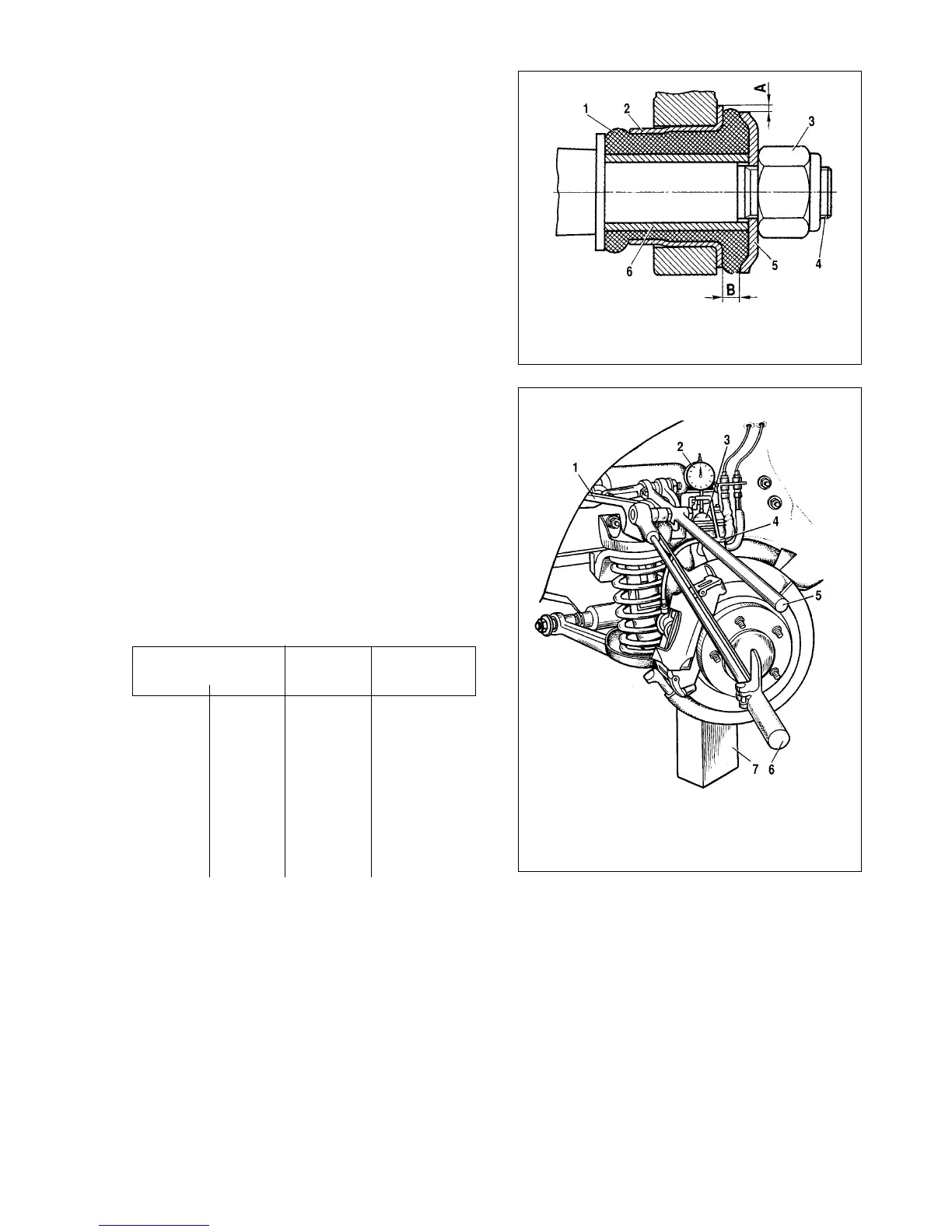
Fig. 4-2. Inspection of the front suspension arm silent block:
1 - rubber bush; 2 - outer bush; 3 - shaft securing nut; 4 - suspension arm shaft;
5 - thrust washer; 6 - inner bush
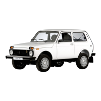
Fig. 4-3. On-vehicle check of the clearance in the suspension upper
balljoint:
1 - upper control arm; 2 - indicator; 3 - upper balljoint housing; 4 - indicator fas-
tening bracket; 5 - control arm; 6 - dynamometer; 7 - block