When necessary, sand the slip rings with emery paper, then
check the winding for continuity or earthing with an ohmmeter or
a test bulb.
Stator - testing
The stator is tested separately after dismantling the alterna-
tor and disconnecting the winding from the diodes.
First test the stator winding for continuity or earthing using an
ohmmeter or a test bulb and battery. The wire insulation should
show no signs of overheating caused by short-circuit in the diode
plate. Always renew the stator with a damaged winding.
Finally, using a special growler, check the stator winding for
internal short-circuit.
Diodes - testing
A sound diode allows current only in one direction. A faulty
diode can either prohibit the current flow (a broken circuit) or
allow it in both directions (a short-circuit).
The complete diode plate must be renewed if any diode is
found damaged.
The diode plate can be checked for a short-circuit with the
alternator in the vehicle. For this disconnect leads from the bat-
tery and alternator and remove the slip ring end housing. Also the
lead to the voltage regulator terminal «Ç» should be disconnect-
ed. In case of the alternator with an old voltage regulator do not
forget to disconnect the voltage regulator terminal «Å» from the
alternator terminal 30.
An ohmmeter or a test bulb (1-5 watt, 12 volts) and battery can
be used as shown in Fig.7-8.
Note. For easier diode fitting three diodes (marked red) make
«positive» rectified voltage. These diodes are «plus» and are
pressed within one diode plate connected to the alternator termi-
nal 30. Three other diodes («minus», marked black) have «neg-
ative» rectified voltage to the housing. They are press-fitted to the
other diode plate connected to earth.
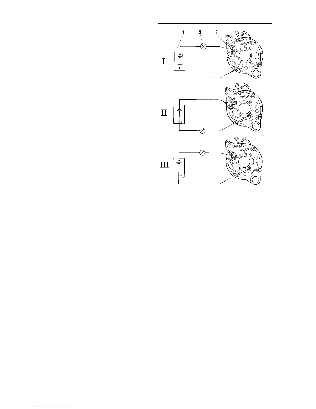
First make sure both positive and negative diodes are not
shorted internally. For this connect the battery positive terminal
through a test bulb to the alternator terminal 30, whilst the nega-
tive terminal - to the alternator housing (Fig.7-8, I). The illuminat-
ed bulb indicates shorted positive and negative diodes.
Short-circuit in the negative diodes can be detected by con-
necting the battery «plus» terminal through a test bulb to one of
the diode plate securing bolts, while the «minus» to the alterna-
tor housing (Fig.7-8, II). The illuminated bulb is an indication of a
short-circuit fault in one or more negative diodes. Note that in the
latter case the bulb may come on as a result of stator winding
being earthed to the alternator housing. However, this fault is
much less frequent than short-circuits in the diodes.
Short-circuit in the positive diodes can be detected by con-
necting the battery «plus» terminal through a test bulb to the
alternator terminal 30, while «minus» - to one of the diode plate
securing bolts (Fig.7-8, III). The illuminated bulb advises about a
short-circuit in one or more positive diodes.
Discontinuity in the diodes can be traced without dismantling
the alternator either by means of an oscilloscope or a tester
through a significant output current drop (20 to 30 percent)
against the specification. If the alternator windings, supplemen-
tary diodes or voltage regulator are sound, whilst the diodes are
not shorted, the cause of the output current drop is discontinuity
in the diodes.
Supplementary diodes - testing
To check the supplementary diodes for short-circuit without
removing and dismantling the alternator, make connections as
shown in Fig.7-9. Similarly to the diode checking, disconnect the
battery and alternator leads, remove the alternator housing, dis-
connect the lead to the voltage regulator terminal «Ç».
Connect the battery positive post through a test bulb (1-3
watt, 12 volts) to the alternator terminal 61, while the negative
post - to one of the diode plate securing bolts.
143
Fig.7-8. Diode check:
1 - battery; 2 - warning light; 3 - alternator; I - concurrent check of positive and
negative diodes; II - check of negative diodes; III - check of positive diodes