When only the Ñ-11Ä plastisol coating is affected, while the
primer is intact, scour any dirt from the relevant areas, then on a
dry surface apply Åèå-1-type plastisol by means of a brush or
airless spray (1.5 mm thick). Allow to dry at ambient temperature
within a day or at 90°ë within 30 minutes.
In the event of major damages of protective layers and dam-
aged primer, clean of dirt and rust the area affected to the bare
metal, then apply Éî-073-type primer on a dry degreased sur-
face. Using a brush, apply Åèå-1-type sealant on the areas pre-
pared.
When the vehicle is in use no longer than 1-1.5 years, it is
recommended to have a minimum overlapping of a new sealant
over an old layer. In the event of a longer field service with this
underbody protection, apply the sealant over the entire under-
body and wheel arches surfaces.
In cold weather before use, store sealant paste in a warm
room to warm it up to at least 20°ë. When thick, thin sealant with
ksylol to 3% as a maximum. Clean the paintwork of excessive
sealant using a cleaning cloth moistened in white spirit.
Body - sealing and tightness
The body tightness is ensured by use of rubber seals (Fig.8-
9), pastes, bodyfillers, sealants, rubber plugs in provisional holes
and thorough levelling of adjoining parts.
When removing or refitting seals with metal reinforcement,
take care not to crumple the metal frame or seal.
Weld seams do not offer an absolute tightness between the
parts, so corrosion is encouraged when water or moisture gets in
between the welded parts. Use Ñ-4Ä-type plastisol on weld
seams to guard off moisture and dirt; apply the 51-É-7 wet-type
sealant (Fig.8-10 and Fig.8-11) on angle joints and clearances:
- between the sidesills and bulkhead (passenger compart-
ment side);
- between the bulkhead and front pillar panel and battery tray;
- between the front chassis arms and radiator support / bulk-
head;
- between the bulkhead and front cover plate;
- between the rear floor / rear floor extensions and rear wheel
arches, bodysides and rear end cross-member.
175
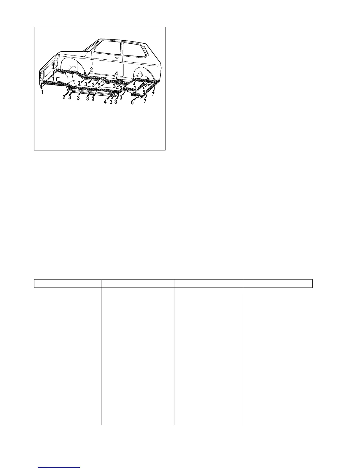
Fig.8-8. Underneath view of the body. Inner cavities of:
1 - front chassis arms; 2 - front chassis arms Òonnections; 3 - middle chassis
arms; 4 - middle chassis arms connectors; 5 - rear floor cross-member; 6 - rear
chassis arms; 7 - rear end cross-member
Table 8-2
Box sections to be corrosion treated
Cavity Injection location Injection direction Notes
Front top cross-member Through two top holes Rightward and leftward Open bonnet
Headlight casings Front (from outside) Over entire surface Remove headlights
Front bottom cross-member Through two holes for bumper fitting Rightward and leftward Remove front bumper
Under front wings Through shielded opening All directions Remove sealing shield
External door sills Through six side holes Forward and backwards Remove moldings
Internal door sills Through hole at the back of sill end Along sills
Front chassis arms Through holes for bumper fitting Along chassis arms Remove front bumper
Front chassis arm connections Through holes underneath body Rightward and leftward Lift vehicle by hoist
Middle and rear chassis arms Through seven holes underneath body Forward and backward Lift vehicle by hoist
Middle chassis arms connections Through holes underneath body Rightward and leftward Lift vehicle by hoist
Rear floor cross-member Through holes in luggage compartment Rightward and leftward Remove trim in luggage compartment
and underneath the body
Rear end cross-member Through holes underneath the body Rightward and leftward Lift vehicle by hoist
Between rear wheel arches and body sides Into cavity openings in luggage compartment Over all surface Remove trim in luggage compartment
Central pillars Into hole behind pillar Downward Remove pillar trim
Front pillars Through 2 holes from interior compartment side Downward Remove pillar trim
Door pockets Through openings in inner door panel Over all bottom inner surface Remove pillar trim