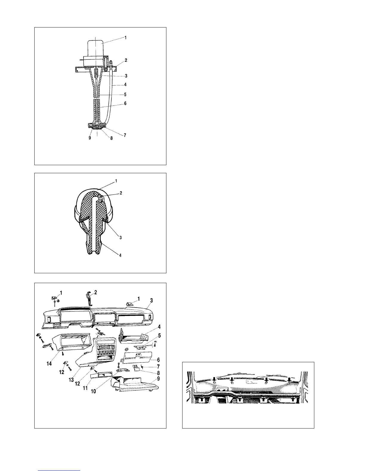
together with the filter gauze. Extract sleeve 3, then carefully tap-
ping rotor 9 shaft 6, push support 7 out and withdraw the shaft
and rotor.
Reassembly is a reversal of dismantling.
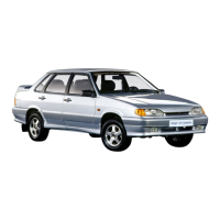
Removal and refitting of washer jets. Working from the
engine bay, slightly squeeze the holders of plastic housing 1
(Fig.8-27), next pick its top with a screwdriver and force the jet
complete with the atomizer. Detach the tube and blow atomizer 2
and housing with compressed air. Refit the jet pushing its hous-
ing strongly into the bore in the body.
Adjust the fluid jet through altering the atomizer position with-
in the socket in the housing. For that insert a needle into the
atomizer hole and carefully swivel the atomizer to direct the fluid
jet where desired.
Instrument panel, seats
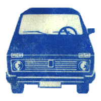
Instrument panel - removal and refitting
Disconnect the battery negative lead.
Remove the windscreen pillar trim, steering column shroud,
instrument panel surround 14 (Fig.8-28), instrument cluster
(Refer to section «Electrical equipment»), disconnect the wiring
connectors and wiring plugs.
Remove the instrument lighting switch knob, undo the retain-
ing nut and push the switch down, behind the instrument panel.
Undo the retaining screws, remove front parcel shelf 9 and
radio support panel 13; disconnect the wiring from the radio, cig-
arette lighter, headlight wipe/wash switch, hazard warning flash-
er switch.
Undo the retaining screws and withdraw glovebox housing 4.
Remove the knobs of the heater control levers. To do this, at
the knob / lever connection point prise out the lower part of the
top knob with some flat and sharp tool, while for the middle and
lower knobs - prise out the upper part.
Undo the four screws (arrowed in Fig.8-29) holding lower
instrument panel 3 (Fig.8-28) to the front cross-member, then
working through the apertures of the glovebox and instrument
panel binnacle, undo four nuts holding the top panel to the front
end, next remove the instrument panel.
181
Fig.8-26. Washer pump:
1 - motor; 2 - reservoir cover; 3 - sleeve; 4 - pick-up tube; 5 - pump housing; 6
- rotor shaft; 7 - rotor shaft support; 8 - rim and filter gauze; 9 - rotor
Fig.8-27. Windscreen and tailgate washer jets:
1 - jet housing; 2 - atomizer; 3 - gasket; 4 - pipe union
Fig.8-28. Instrument panel components:
1 - bracket; 2 - reinforcement; 3 - instrument panel; 4 - glovebox housing; 5 - lid
catch; 6 - glovebox lid; 7 - spring; 8 - lid latch; 9 - shelf; 10 - lid hinge link; 11 -
trinket tray; 12 - retaining clips; 13 - radio support panel; 14 - instrument panel
surround
Fig.8-29. Instrument panel attachment points (arrowed).