197
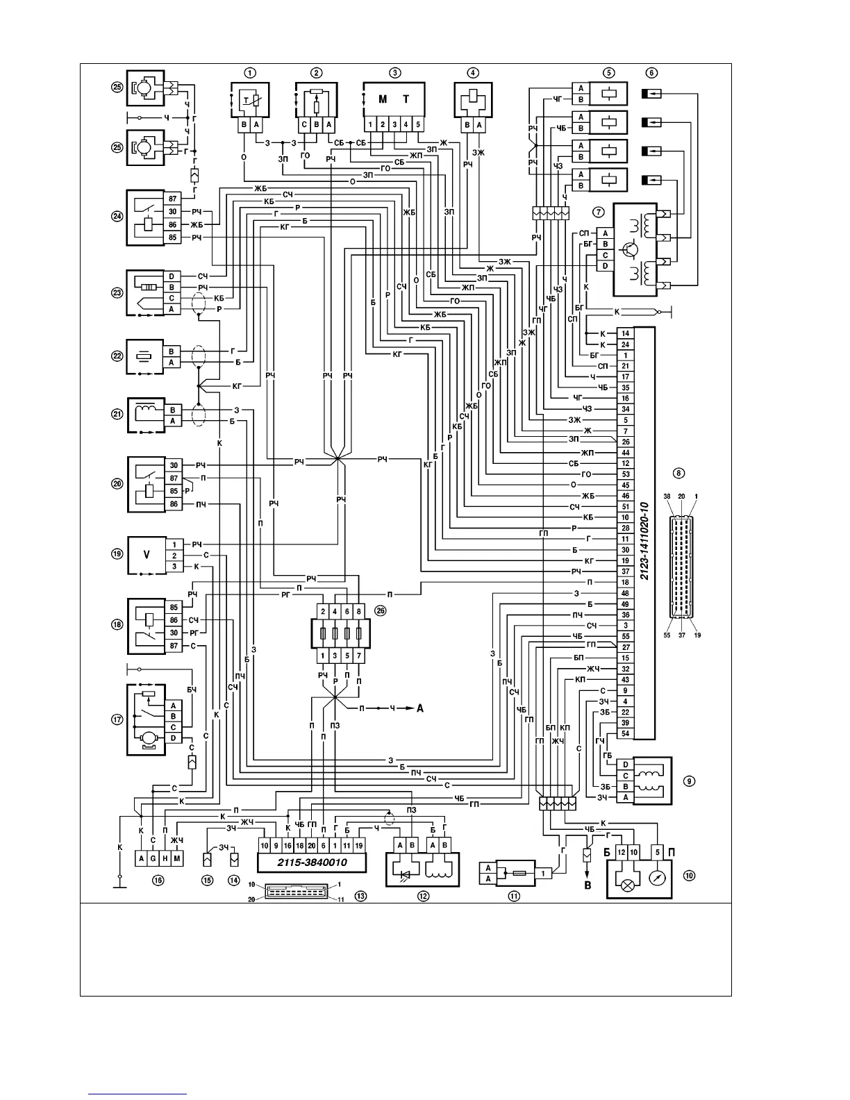
Fig.9-16. EMS wiring diagram (Sequential Fuel Injection), VAZ-21214-20 vehicle:
1 - coolant temperature sensor; 2 - throttle position sensor; 3 - mass airflow meter; 4 - canister purge solenoid; 5 - injectors; 6 - spark plugs; 7 - ignition module; 8 - elec-
tronic control unit; 9 - idle air control valve; 10 - instrument cluster with tachometer and CHECK ENGINE light; 11 - main fusebox; 12 - LED, antitheft system ; 13 - control
module, antitheft system; 14 - to door courtesy light switch; 15 - to interior light switch; 16 - diagnostic plug; 17 - electric fuel pump and fuel level sender; 18 - fuel pump
relay; 19 - speed sender; 20 - main relay; 21 - crankshaft position sender; 22 - knock sensor; 23 - oxygen sensor; 24 - fan relay; 25 - electric fans; 26 - injection system
fusebox; Ä - to power supply