Oil pump shaft and drive gears
Check to see there is no denting or scuffing of the shaft bear-
ing journals or eccentric cam surfaces.
No pitting of the oil pump gears or ignition distributor is per-
mitted, if this is the case, renew the gears and shaft.
Oil pump shaft bushes. Check the inner diameter of the
bushes, their proper fitting, make certain the oil port in the front
bush is aligned against the oilway in the cylinder block (bush turn-
ing). The inner surface must be smooth and without scuffs.
Measure the diameter of the shaft and bushes to determine
the clearances between the bushes and shaft bearing surfaces.
When the clearance is over 0.15 mm (limit wear value), or in case
of damaged or loose bushes, renew the bushes.
For removal and refitting use tool Ä.60333/1/2 (Fig. 2-73),
observing the following:
- the bushes must be pressed in place with the oil port in the
front bush aligned against the oilway in the cylinder block;
- after pressing in, the bushes are machined to the final inner
diameter (Refer to Fig.2-68 for the sizes). For optimum concentric-
ity of the shaft bushes, use the finishing reamer Ä.90353 for con-
current machining of both bushes.
Oil pump inner gear bush. Check the bush is adequately
pressed in. The inner surface should be smooth, with no scuffs,
otherwise renew the bush.
Use tool Ä.60326/R for bush pressing-in or out (Fig.2-74).
After pressing-in, ream the bush to 16.016-16.037 mm.
41
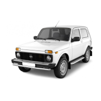
Fig.2-69. Dismantling the oil pump:
1 - relief valve; 2 - valve spring; 3 - cover; 4 - housing; 5 - shaft
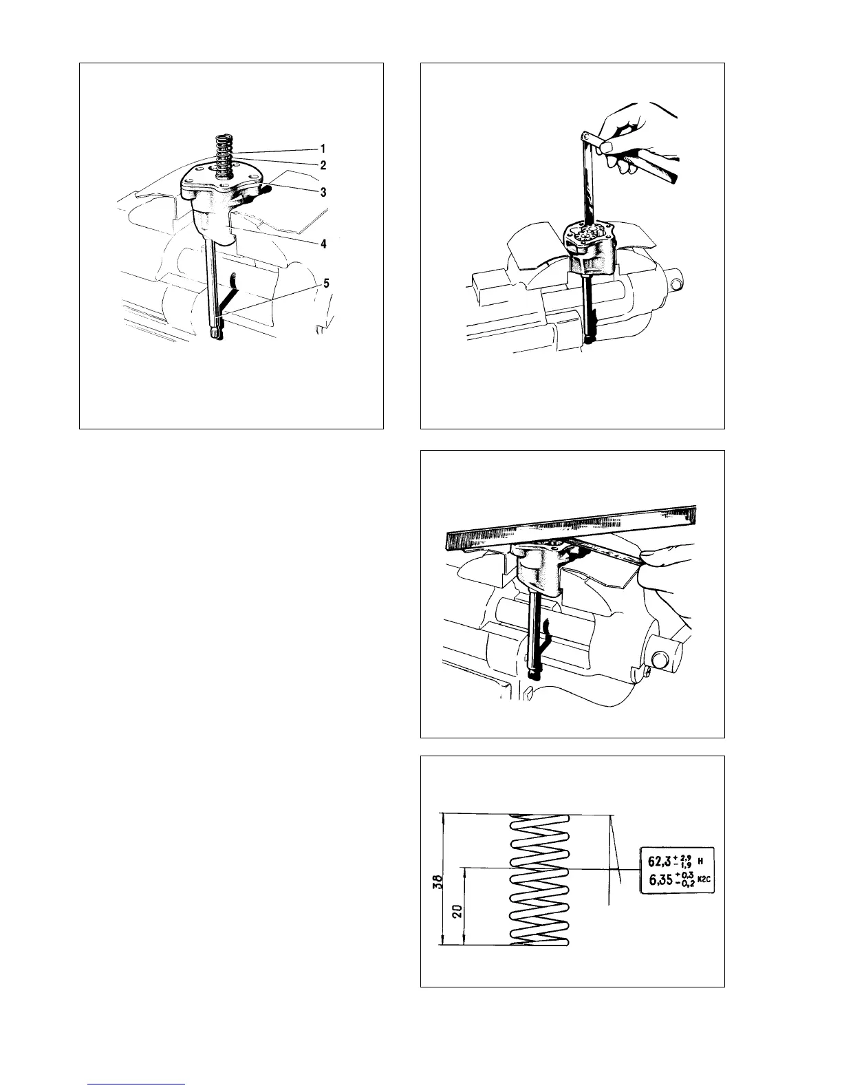
Fig. 2-70. Checking the oil pump radial play
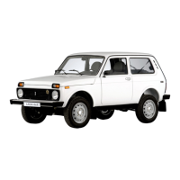
Fig. 2-71. Checking the oil pump endfloat
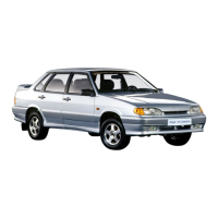
Fig.2-72. Basic data for checking the relief valve spring