Disconnect hoses 7 and 8 (supply and return) (Fig.9-6) from
pipes 1 and 9. Plug the hose / pipe ends to prevent dirt ingress.
Disconnect accelerator cable 4 (Fig.9-7) from sector 6 on the
throttle hosing, bracket 5 on the receiver unit and from bracket 3
on valve cover.
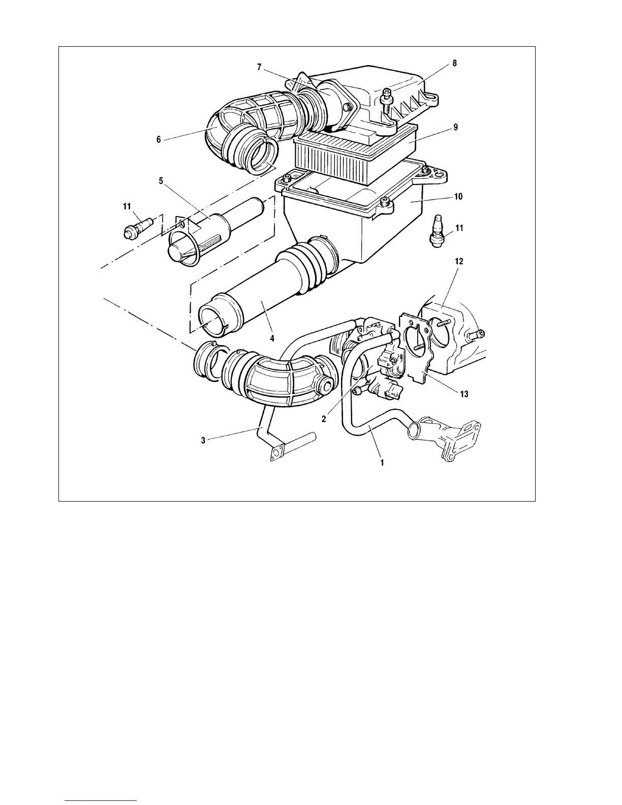
Disconnect the crankcase evap hose from hose 6 (Fig.9-8)
connection, loosen two clips and remove hose 6 of the intake
manifold. Cut off three rubber mountings 11 holding the air clean-
er to the body and one mounting that retains the cold air intake
end to the radiator, remove the air cleaner complete with mass air
flow meter 7.
From the receiver unit disconnect the vacuum hose to the fuel
pressure regulator and to the brake servo unit.
Disconnect the canister purge hose from the throttle housing
(when the vehicle is fitted with the evaporative emission control
system).
Disconnect the wiring from the throttle manifold, ignition mod-
ule, injector wiring harness, all relevant sensors on the power unit
and from reversing light switch on the transmission.
Next proceed with the usual removal procedure as described
in chapter 2.
Refitting is the reverse order of removal. The rubber mount-
ings of the air cleaner are disposal, so new mountings must be fit-
ted when refitting the air cleaner.
After refitting the power unit, adjust the accelerator drive. At
fully released accelerator pedal 7 (Fig. 9-7), the throttle should be
fully closed. The cable should be taut. The cable deflection by
hand force should be 10 mm as a maximum. When necessary,
adjust the cable tension using the adjuster nuts at the cable end.
At fully depressed accelerator pedal, the throttle should be
wide open, throttle sector 6 should have no further movement.
191
Fig.9-8. Removing the components and units of air intake system:
1 - part throttle channel heater hose; 2 - throttle body; 3 - return hose from throttle body; 4 - air intake; 5 - air intake end piece; 6 - intake manifold hose; 7 - MAF sensor;
8 - air cleaner cover; 9 - filtering element; 10 - air filter housing; 11 - filter mounting; 12 - receiver unit; 13 - gasket