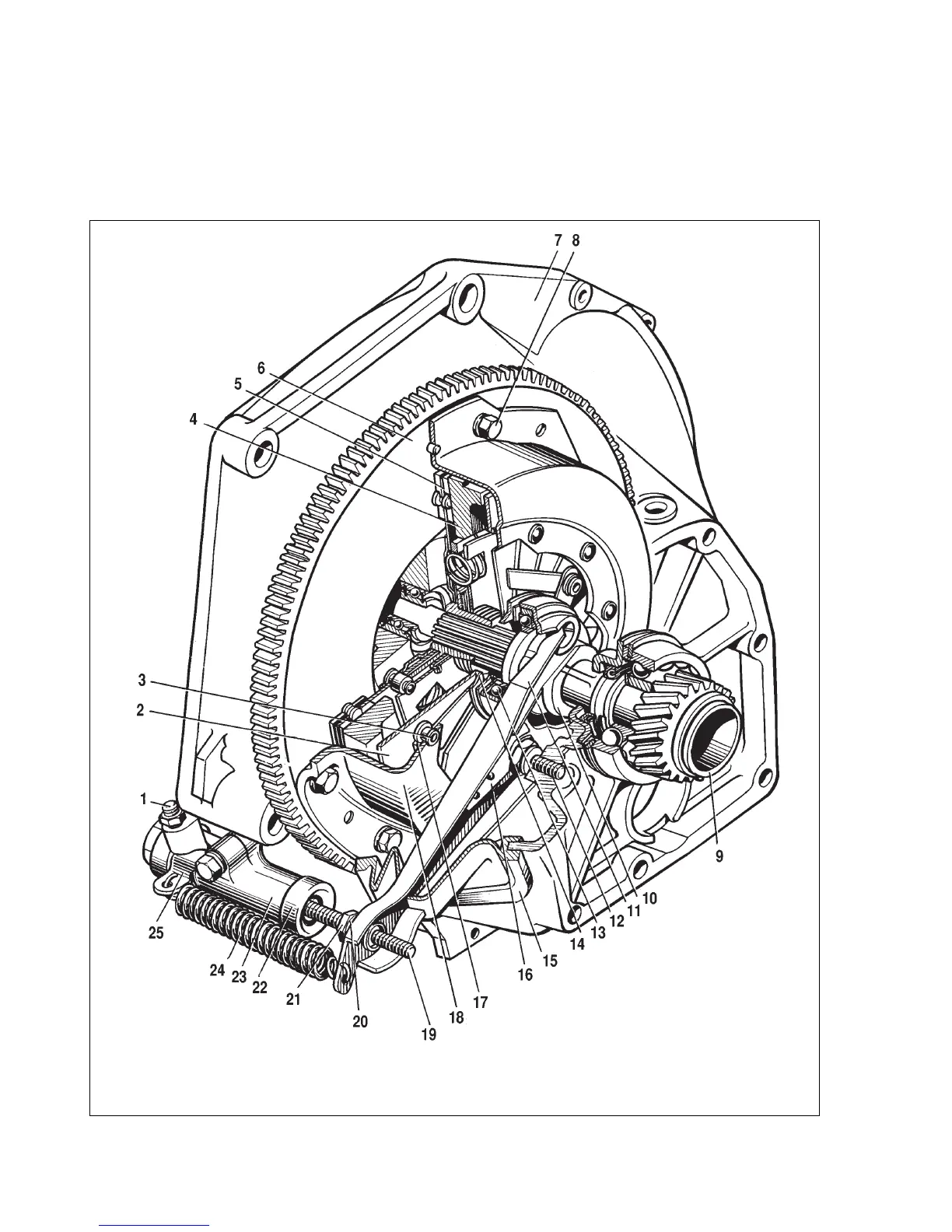
The design of the clutch is shown on fig. 3-1. The clutch release fork 11 (fig. 3-1) can be of two types: with a leaf or wire spring.
Chapter 3. Power train
Clutch
57
Fig. 3-1. Clutch assembly:
1 - bleeder; 2 - central diaphragm spring; 3 - diaphragm spring rivet; 4 - pressure plate; 5 - clutch disc; 6 - flywheel; 7 - clutch bellhousing; 8 - bellhousing-to-flywheel bolt;
9 - gearbox input shaft; 10 - clutch release bearing assembly; 11 - clutch release fork; 12 - release fork ball socket; 13 - clutch release bearing; 14 - pressure plate thrust
flange; 15 - clutch release fork boot; 16 - clutch release fork spring; 17 - pressure plate fulcrum ring; 18 - clutch cover; 19 - clutch release fork pushrod; 20 - adjusting nut;
21 - locknut; 22 - protective cap; 23 - clutch release cylinder (slave cylinder); 24 - fork return spring; 25 - return spring bracket