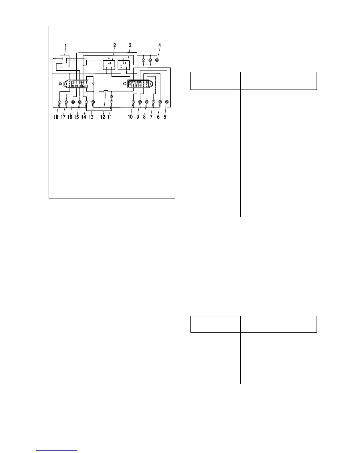
Connector ï2 (any colour, except red and amber)
1 -
2 To high beam relay
3 To exterior lighting switch
4 -
5 To indicators flasher relay
6 To alternator terminal «Ç»
7 -
8 To rear foglight switch
9 To heated rear window switch
10 To ignition switch terminal «15»
11 To fuel level sensor terminal «T»
12 To coolant temperature sender
13 To coolant temperature sender
Coolant temperature gauge - Òhecking. The coolant tem-
perature gauge is associated with the relevant sender in the
cylinder head. At the sensor resistance of 640-1320 Ohm the
needle should be at the low end of scale, at 77-89 éhm it should
rest at the front of the red area, at resistance of 40-50 Ohm the
needle should go to the end of the red area.
Fuel level gauge - Òhecking. The fuel gauge is associated
with the relevant sensor in the petrol tank. The same sensor
operates the fuel reserve warning light, when 4 to 6 litres are left
in the petrol tank. At the sensor resistance of 200-238 Ohm the
needle should at the low end of scale, at 59-71 Ohm - at the mid-
dle scale, while at 17-23 Ohm the needle should go to the high
end of scale (mark 1).
Speedometer - checking. Check the speedometer turning
its drive shaft at various speeds. The data required for checking
is shown in Fig.9-4.
Table 9-4
Speedometer specification
Speedometer Drive shaft
readings, km/h speed, rpm
30 433 - 500
40 600 - 667
50 766 - 833
60 933 - 1000
80 1250 - 1333
100 1567 - 1667
120 1883 - 2000
140 2200 - 2333
160 2517 - 2667
Tachometer - checking. The tachometer operates on the
principle of measuring the voltage pulse frequency in the alter-
nator field winding.
The tachometer is checked on a test bench simulating the
vehicle ignition system. Connect the tachometer as applicable,
apply 14 volts to the primary circuit and set the spark gap at 7
mm. Turn the ignition distributor shaft at such a speed to bring
the tachometer needle to one of main scale divisions. At this
moment the ignition distributor shaft speed should be within the
permissible limits (Refer to Table 9-5).
Table 9-5
Tachometer specification
Tachometer Ignition distributor
reading, rpm shaft speed, rpm
1000 900 - 1100
2000 1900 - 2250
3000 2950 - 3300
4000 3950 - 4300
Fuel level sender - checking. With an empty tank the sen-
sor resistance should be (250±10) Ohm, with a half-filled tank -
(66±6) Ohm, with a full tank - (20±2) Ohm.
208
Fig.9-36. Wiring diagram for instrument cluster:
1 - digital tachometer; 2 - coolant temperature gauge; 3 - fuel level gauge; 4 -
instrument illumination light; 5 - engine overheating warning light; 6 - heated
rear window warning light; 7 - rear fog light warning light; 8 - high beam warn-
ing light; 9 - exterior lighting warning light; 10 - direction indicator warning light;
11 - low battery warning light; 12 - resistor, 50 éhm, 5 W; 13 - brake failure
warning light; 14 - low oil pressure warning light; 15 - differential lock-up warn-
ing light; 16 - fuel reserve warning light; 17 - seat belt reminder; 18 - handbrake-
on warning light Connector «ï1» is red or orange