When sparking occurs at the pressure below 0.3 åPa (3
kgf/Òm
2
), the spark plug is defective.
Only a few sparks are allowed in the spark gap; when no
sparking is observed either on the spark plug or in the spark gap,
it is likely that the insulation is cracked and the central electrode
arcs internally to earth. Always discard such spark plugs.
Ignition switch
Check the ignition switch contacts are closing properly at dif-
ferent key positions (Table 7-5) and theft-deterrent device is func-
tional. The battery and alternator voltage is supplied to terminals
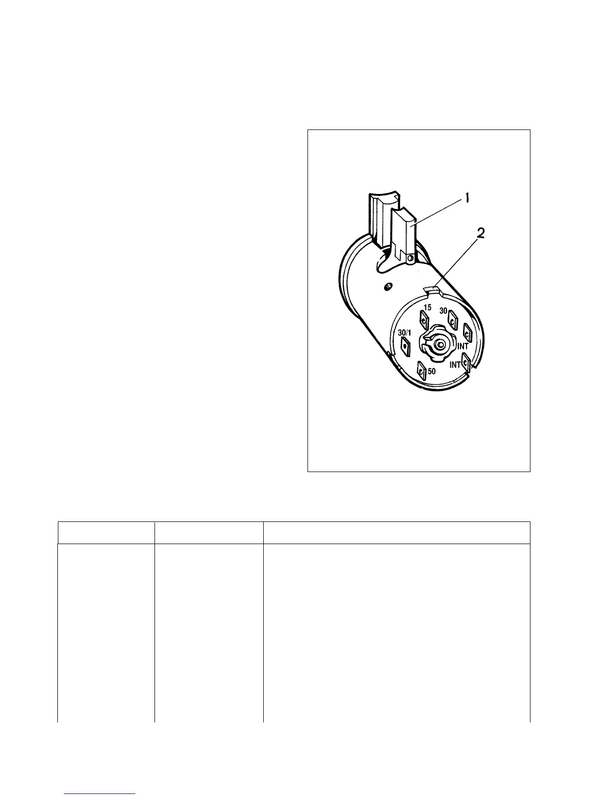
30 and 30/1. The vacant terminal «INT» is intended for radio/cas-
sette player connection.
The steering lock pin moves out when the key is turned to
position III «parking» and is then removed from the switch. The
lock pin moves in after the ignition key is turned from position III
«parking» to position 0 «ignition off». The key can only be
removed from position III.
When inserting the contact part into the ignition switch hous-
ing, locate it so that terminals 15 and 30 are on the lock pin side
(Fig.7-27), ensure the wider end of the contact part is well within
the wider slot of the ignition switch housing.
Suppression components - testing
The following is used for interference suppression:
- 1 kOhm resistor in the distributor rotor arm;
- resistive HT cables of (2000±200) Ohm/m for red leads
(èÇÇè-8) or (2550±270) Ohm/m for blue leads (èÇèèÇ-40);
- 4-10 kOhm resistors in the spark plugs;
- 2.2 microfarad capacitor in the alternator.
The leads and resistors are checked with an ohmmeter. Refer
to subsection «Alternator» for the capacitor checking procedure.
Lighting and signalling
155
Fig.7-27. Ignition switch contact unit:
1 - lock pin; 2 - wider part of contact unit
Table 7-5
Circuits activated at different ignition switch positions
Position Live contacts Circuits activated
0 (Off) 30 and 30/1
–
I (Ignition) 30-INT –
30/1-15 Alternator field winding. Ignition system. Direction indicators. Instruments.
Heater unit. Heated rear window. Wipers: windscreen, rear window, headlight .
II (Starter motor) 30-INT
–
30/1-15 Refer to position I
30-50 Starter motor
III (Parking) 30-INT