189
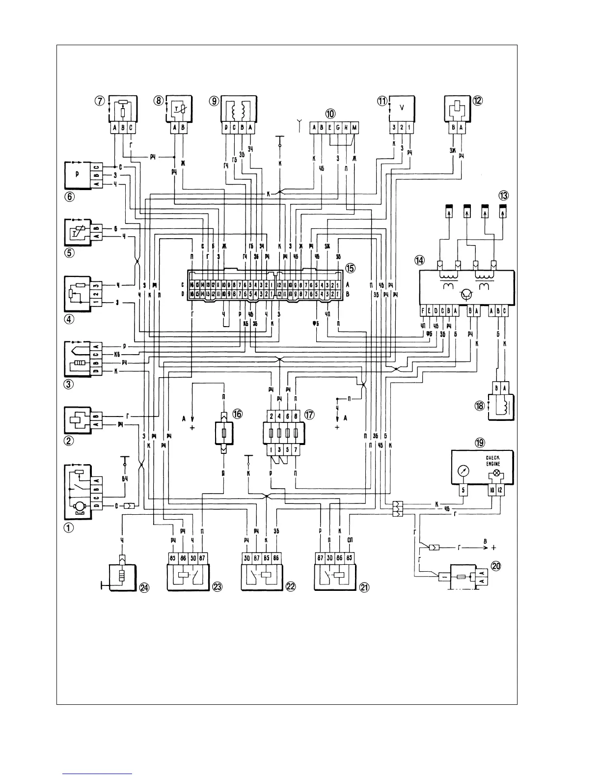
Fig.9-5. Wiring diagram for VAZ-21214 vehicle, CFI:
1 - electric fuel pump and fuel level sender; 2 - injector; 3 - oxygen sensor; 4 - octane potentiometer; 5 - air temperature sensor; 6 - MAP sensor; 7 - throttle position sen-
sor; 8 - coolant temperature sensor; 9 - idle air control valve; 10 - diagnostic plug; 11- speed sender; 12 - canister purge valve; 13 - spark plugs; 14 - ignition module;
15 - electronic control unit plug; 16 - intake manifold preheater fuse; 17 - fusebox, injection system; 18 - crankshaft position sensor; 19 - instrument cluster with tachometer
and «CHECK ENGINE» light; 20 - main fusebox; 21 - ignition relay; 22 - fuel pump cut-in relay; 23 - intake manifold preheater relay; 24 - intake manifold preheater;
Ä - to battery «+» terminal; Ç - to ignition switch terminal «15»