Headlight wipe/wash. The vehicle VAZ-21215-10 is not fit-
ted with the headlight wipe/wash.
Cooling fan motor. Two dc motors powered from constant
magnets of MP 8019/37 type are provided to operate the engine
cooling fan blower. The wiring diagram for cooling fan motor is
shown in Fig.9-34.
The motors are triggered by sensor 1 through complementary
relay 3. The sensor is fitted to the right-hand radiator cooler. The
sensor contacts close at (99±3)°ë and open at (94±3)°ë. The
relay is housed in the engine bay and is bolted to the top bulk-
head reinforcement.
The motors are maintenance-free and must always be
renewed in case of failure.
Motor specification
Nominal motor shaft speed with impeller
load, rpm . . . . . . . . . . . . . . . . . . . . . . . . . . . . . . . . . .600-2800
Current consumption at speed and
load as specified, ampere, not greater . . . . . . . . . . . . . . . . .14
Instrument cluster. The instrument cluster includes:
speedometer with trip counter, coolant temperature gauge, fuel
gauge, tachometer, 13 warning lights (Fig.9-35). The wiring dia-
gram for instrument cluster is shown in Fig.9-36. The instrument
panel pin assignment is shown in Table 9-3.
205
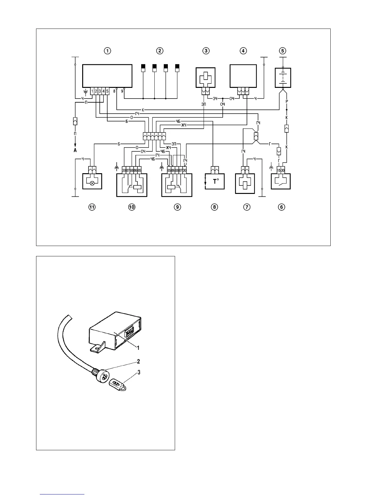
Fig.9-28. Wiring diagram for Engine Management System:
1 - glow plug control module; 2 - glow plugs; 3 - EGR valve; 4 - fuel pump; 5 - battery; 6 - ignition switch; 7 - breaker; 8 - thermoswitch; 9 - relay, EGR valve; 10 - relay,
thermoswitch; 11 - glow plug warning light
Fig.9-29. Automotive theft-deterrent system:
1 - control module; 2 - LED for system state indication; 3 - key fob