EasyManuals Logo
Home>Veeder-Root>Measuring Instruments>EMR4

Veeder-Root EMR4 Application Guide

Veeder-Root EMR4
71 pages
To Next Page IconTo Next Page
To Previous Page IconTo Previous Page
Page #46 background imageLoading...
Page #46 background image
41
EMR
3
- Truck Installations
EMR4 Truck Installation Installing the Remote Display (Optional)
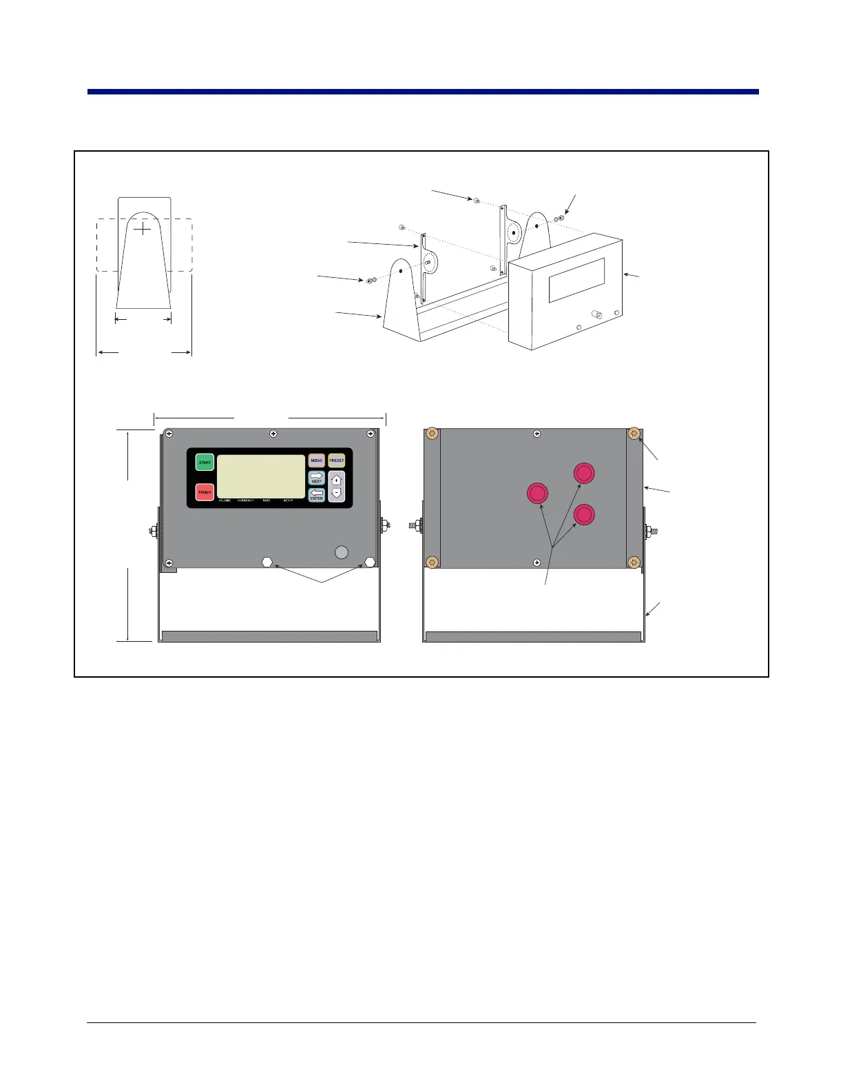
Figure 33. Remote Display Assembly
Front View Rear View
Mounting bracket kit
(P/N 845900-024)
Plastic caps (remove
for cable entry)
These 2 hex head bolts are drilled
through for sealing the front cover
C&C switch
#30 Torx screws (4)
758-27.eps
#30 Torx screws (4) fasten into back of
Remote Display housing
Adjust mounting strips to desired
indents each side, then tighten nuts
Mounting Strips shown
in low position (2)
1 Nut and 1 lockwasher
each side
Base
Mounting Strips
shown in high
position
Assembly of Remote Display
Head Mounting Bracket
Side view
8.625"
(220 mm)
high position
or
6.625"
(168 mm)
low position
9.5"
(240 mm)
3.25"
(83 mm)
5.625"
(143 mm)
Remote Display Head
(P/N 84559X-002)

Table of Contents

Other manuals for Veeder-Root EMR4

Questions and Answers:

Question and Answer IconNeed help?

Do you have a question about the Veeder-Root EMR4 and is the answer not in the manual?

Veeder-Root EMR4 Specifications

General IconGeneral
BrandVeeder-Root
ModelEMR4
CategoryMeasuring Instruments
LanguageEnglish

Related product manuals