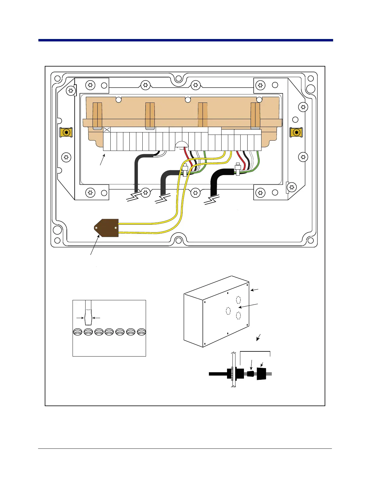
Figure 34. Remote Display Connections (Rear Cover Removed)
Rear cover of
Remote Display
Front panel
C&C switch
Remote Display
terminal block
Remove a plastic cap from one
of the rear access ports to install
input cable(s)
Cord grip
Nut
To external device
9/64” (3.5 mm) max.
To terminal
block
Bushing
Remote Display (rear cover removed)
Cable entries to Remote Display
Attaching wires to
terminal block
GRN
IB-A
INTERCONNECT BOX
1000 RPM ENCODER OPTIONAL KEYPADTEMP PRBINTERLOCK
STOP SWC & C SW
BLK
GND
WHT
IB-B
RED
PWR
YEL
+
YEL
GND
WHT
+
BLK
GND
GRN
CHA
WHT
CHB
BLK
GND
RED
+5V
WHT
+
BLK
GND
WHT
+
BLK
GND
ORA
KP8
BLU
KP7
YEL
KP6
GRN
KP5
WHT
KP4
BLK
KP3
RED
KP2
NOT
USED
Note: Maximum screwdriver
size for attaching wires to
terminal block.

 Loading...


