VTK‐VS‐BA‐004e‐B|UserManualMDS3200A | Initial Operation
27
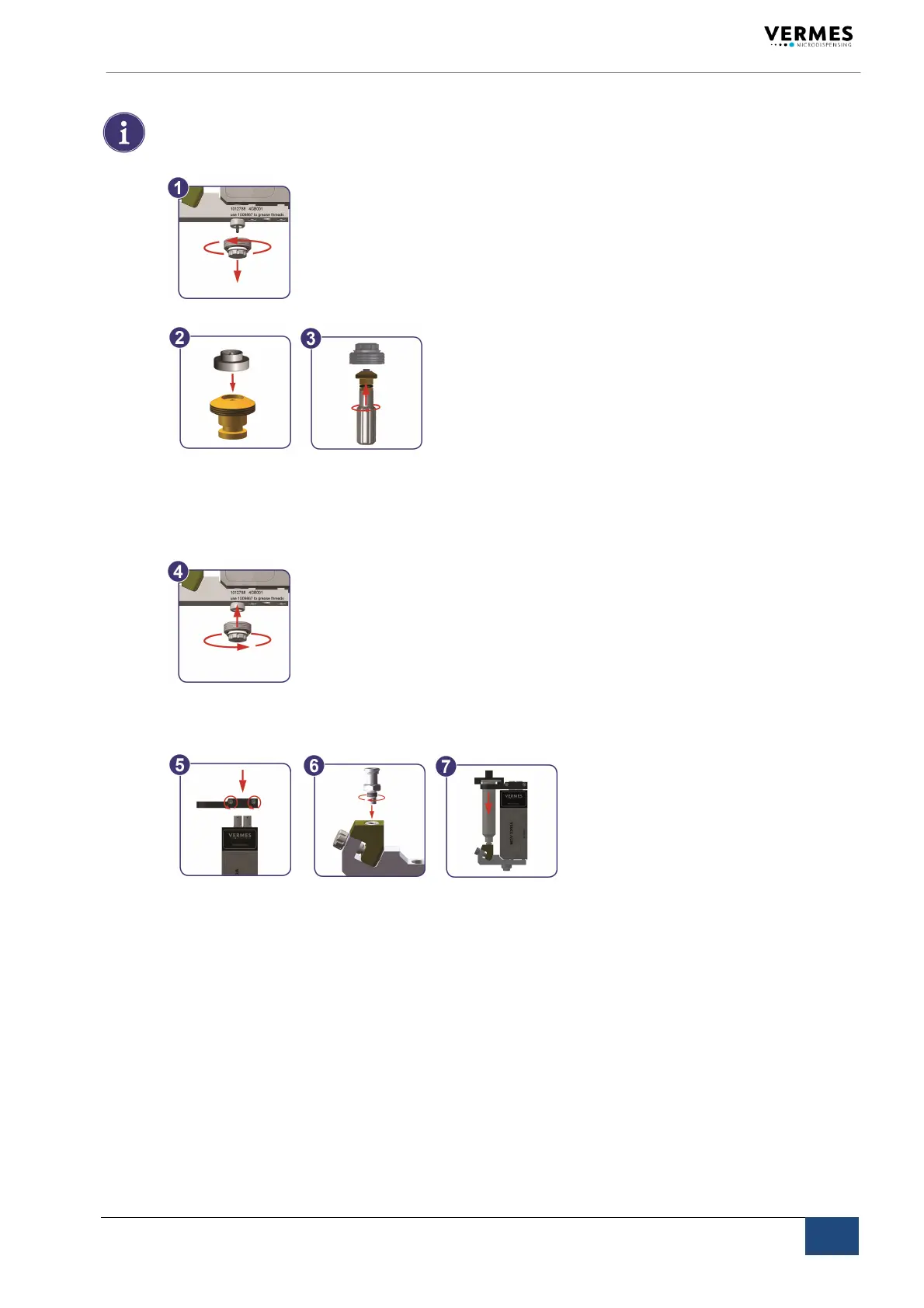
5.2 AssemblingtheMDV3200A
INFORMATION!(somepartspre‐assembled)
Someelementsoftheequipmentaredeliveredinpreassembledstate.
Proceedasfollows:
Step1:Separatethenozzleunitfromthefluidbox.(1)
Step2:Mountanozzleinsert.(2+3)
Unscrewthetappetguidancefromthenozzleadjustingnut.Use
thenozzleexchanging
toolMDT303.
Placethenozzleinsertontothetipofthetappetguidance;thelargefaceofthenozzle
inserthastopointdown.Firmlyreattachthetappetguidancetothenozzleadjustingnut.
Step3:Mountthenozzleunit.(4)
Screw
theassemblednozzleunit(tappetguidancewithseal,nozzleadjustingnutand
nozzleinsert)tothefluidbox(2‐3rotations,tobeexecutedmanually).
Step4:Installthefluidsupply.(5+6+7)
SlidethecartridgeholderoverthesensorandactuatorsocketoftheMDV3200A.The
screwsmustbelocatedonthelabeledsideofthevalve.
Tightenthetwohexscrews.
ScrewtheLuer‐LockconnectorintothecartridgebaseCC.
PlacethecartridgeitselfintothecartridgeholderandconnectittotheLuer‐Lockfluid
boxconnector,screwingclockwise.
5.3 InstallationoftheMDS3200A
Priortoinstallation,verifytheconditionsintheintendedlocation,withrespecttothespeci‐
ficationofthesystemandinformationdetailedinthischapter.Thecontrolunitandthe
valvehavetobeinstalledstrictlyinconformitywiththeproceduresdescribedbelow.The
systemrequires:
Powersupply
Pneumatic
supply