VTK‐VS‐BA‐004e‐B|UserManualMDS3200A | Initial Operation
30
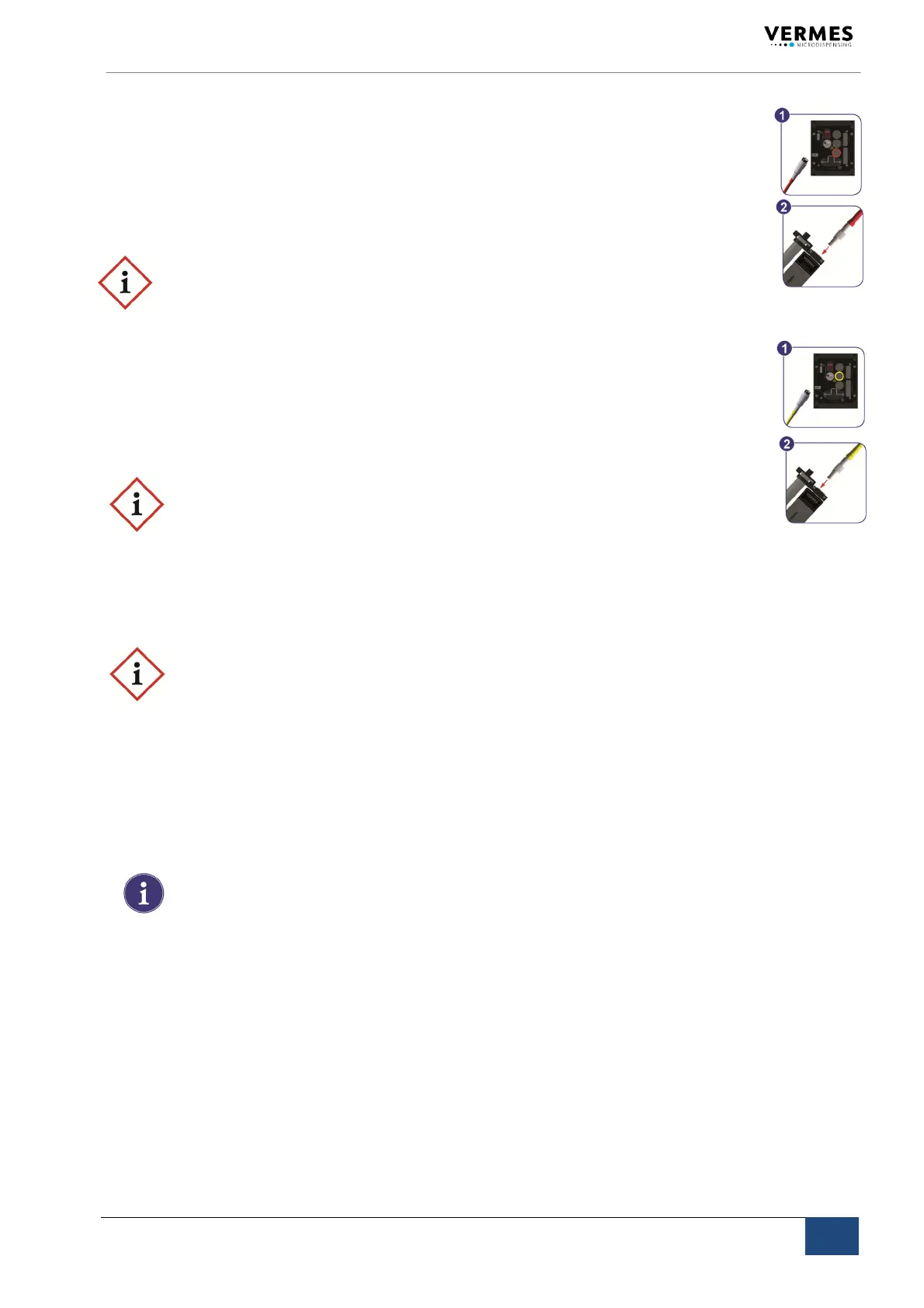
5.3.4.1 ActuatorCable
Powertothepiezoelementissuppliedbytheactuatorcable,whichiswrappedwithared
antikinksleeve.Thevoltagerangeis‐30Vto120V(bipolaroperation).
Step1: Plugthecableintothecorrespondinglylabeledconnectorontherearsideofthe
control
unitandscrewitinplace.
Step2: Theotherend,equippedwithaLEMOconnector(corrugatedsleeve),hastobe
insertedtothefour‐pinbushingofthevalve.
IMPORTANTNOTE!(Connectingcables )
Verifyduringtheconnectingprocedurethattheredpointsonplugandsocketpoint
towardseach
other.
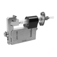
5.3.4.2 SensorCable
Thisyellowcableisprovidedtotransferdatafromthesensorintegratedinthevalvetothe
controlunit.Theconnectionhastobeperformedasdescribedabove.
Step1: Firstfixittothecorrespondingsocketofthecontrolunit.
Step2: Theconnectorwith
corrugatedsleevehastobeattachedtothe5pinsocket
ofthevalve.
IMPORTANTNOTE!(Connectingcables )
Verifyduringtheconnectingprocedurethattheredpointsonplugandsocketpoint
towardseachother.
5.3.4.3 MainsCable
Theblackmainscablesuppliesthepowertothecontrolunit.
IMPORTANTNOTE!(typeplate)
Donotconnectthesystemtothemains,beforehavingcheckedthetypeplateofthe
modeltobeinstalled(mainsvoltage,110VACor220VAC).
Step1: Plugthecableintothesocketatthebottomoftherearsideofthecontrolunit.
Therearsideisillustratedinchapter4.
Step2: Aspecialshackleisprovided,locatedjustabovethesocket.Usethisshackletose‐
curethemainscablefromslippingoff.
Step3: Connectthecabletothepowersupply.
Step4: PressON/OFFbutton,locatedontherearside
ofthecontrolunit.
INFORMATION!(valvenot connected)
Ifthevalveisnotconnected,anerrormessage(“VALVENOTPRESENT“)appearson
thescreen.SwitchOFFthesystem,disconnectitfromthemainsandcompletethe
installationbeforecontinuing.