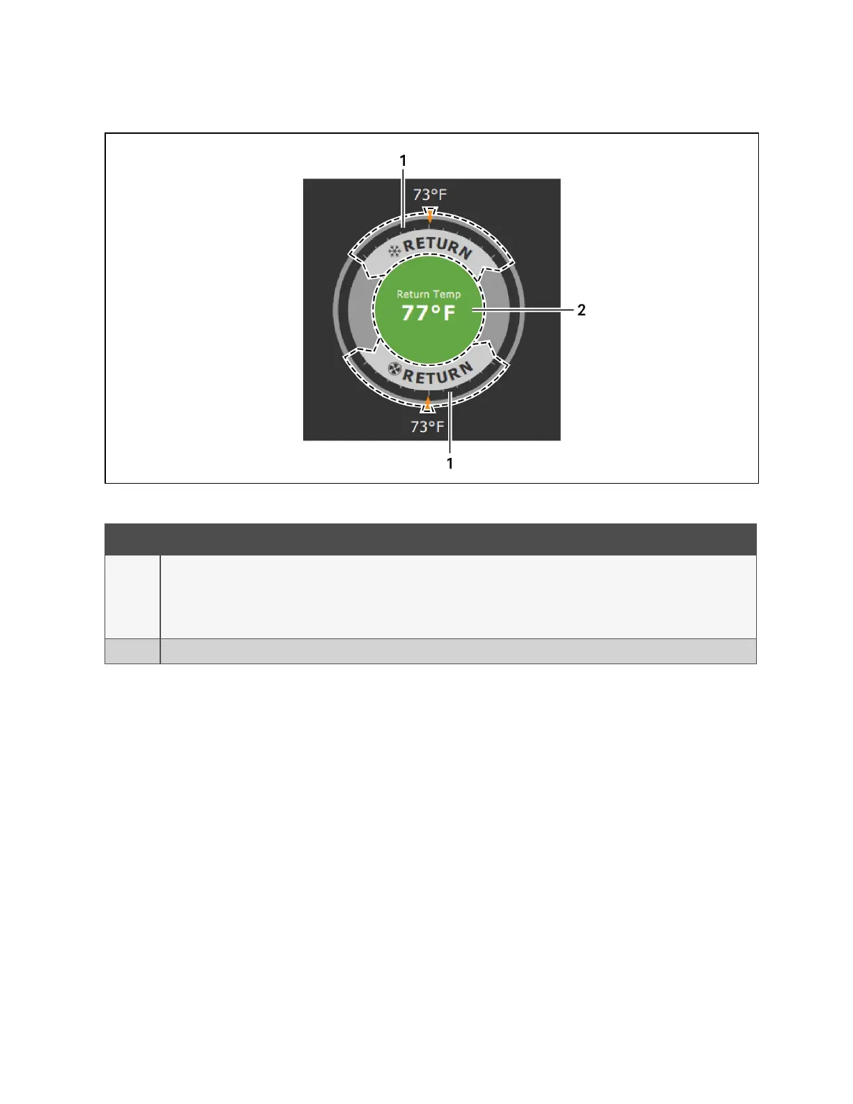
Figure 1.2 Dial Sections
Item Description
1
Control sensor and its setpoint. The sensors and setpoints displayed depend on the configuration of your unit.
You may see only temperature-control, or if the unit includes humidity control, that displays on the dial as well.
If the sensor selected for fan control is the same as that selected for temperature control, the dial displays the fan control sensor and
setpoint, as shown in Figure 1.2 above .
2 Single or multiple sensor readings. Cycle through readings by touching the displayed reading.
Table 1.2 Dial Sections
1 Getting Started with Vertiv™ Liebert® iCOM™Installer/User Guide
4
Vertiv™ Liebert® iCOM™Installer/User Guide