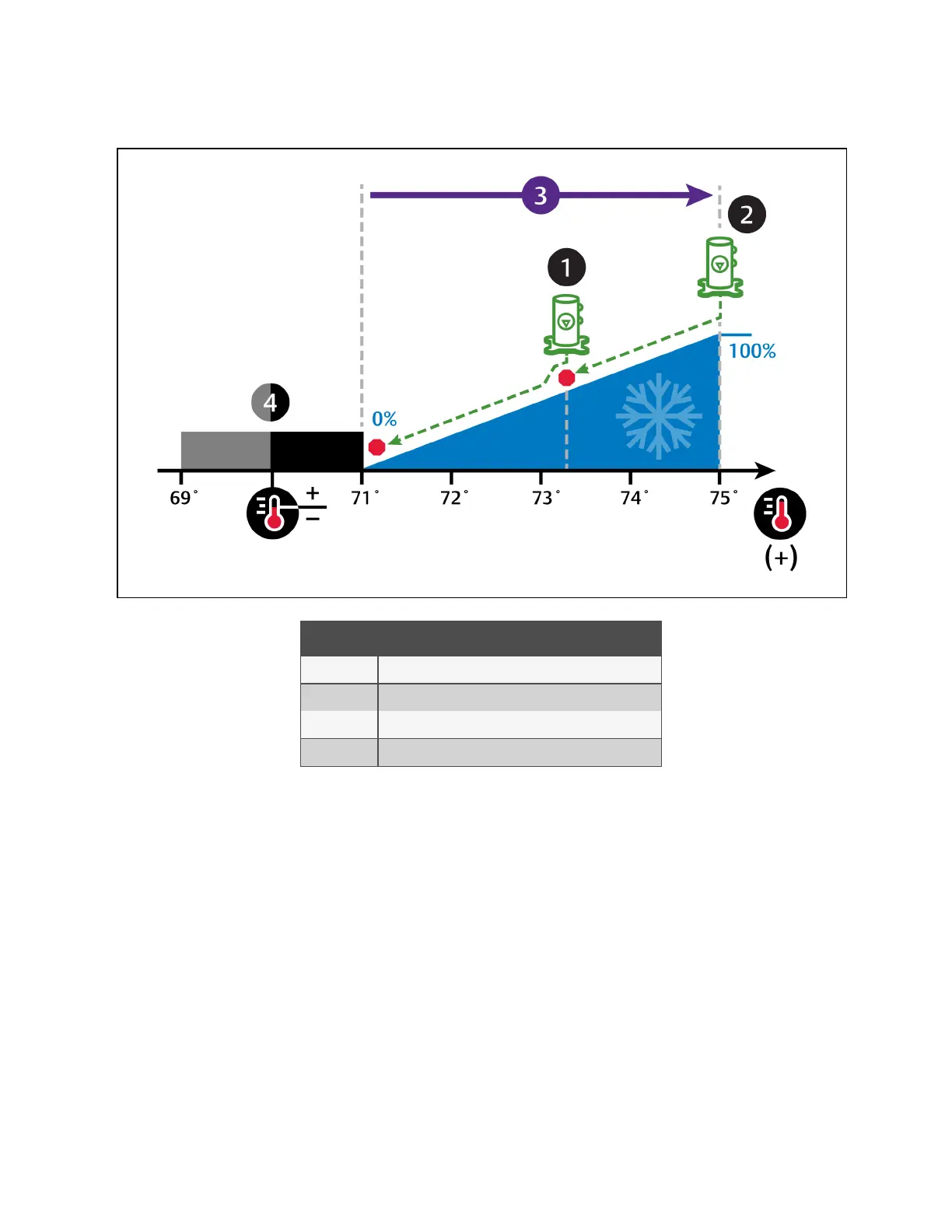
Figure 3.5 Compressor Control—Two Step Capacity Using One Scroll Compressor with Unloaders
Number Description
1 Scroll compressor unloaded.
2 Scroll compressor loaded.
3 ½ of proportional band.
4 Deadband.
Two Scroll Compressors with Unloaders
• 70° setpoint
• 8° proportional band
• 2° deadband
In Figure 3.6 on the facing page :
Compressor 1 starts unloaded when the cooling requirement is 33% and continues to operate until the cooling requirement is
17% or, if the cooling requirement reaches 80%, Compressor 1 operates loaded until the requirement is 70%.
Compressor 2 starts unloaded when the cooling requirement is 63% and continues to operate until the cooling requirement is
47% or, if the cooling requirement reaches 100%, Compressor 2 operates loaded until the requirement is 90%.
3 Service Operation
32
Vertiv™ Liebert® iCOM™Installer/User Guide