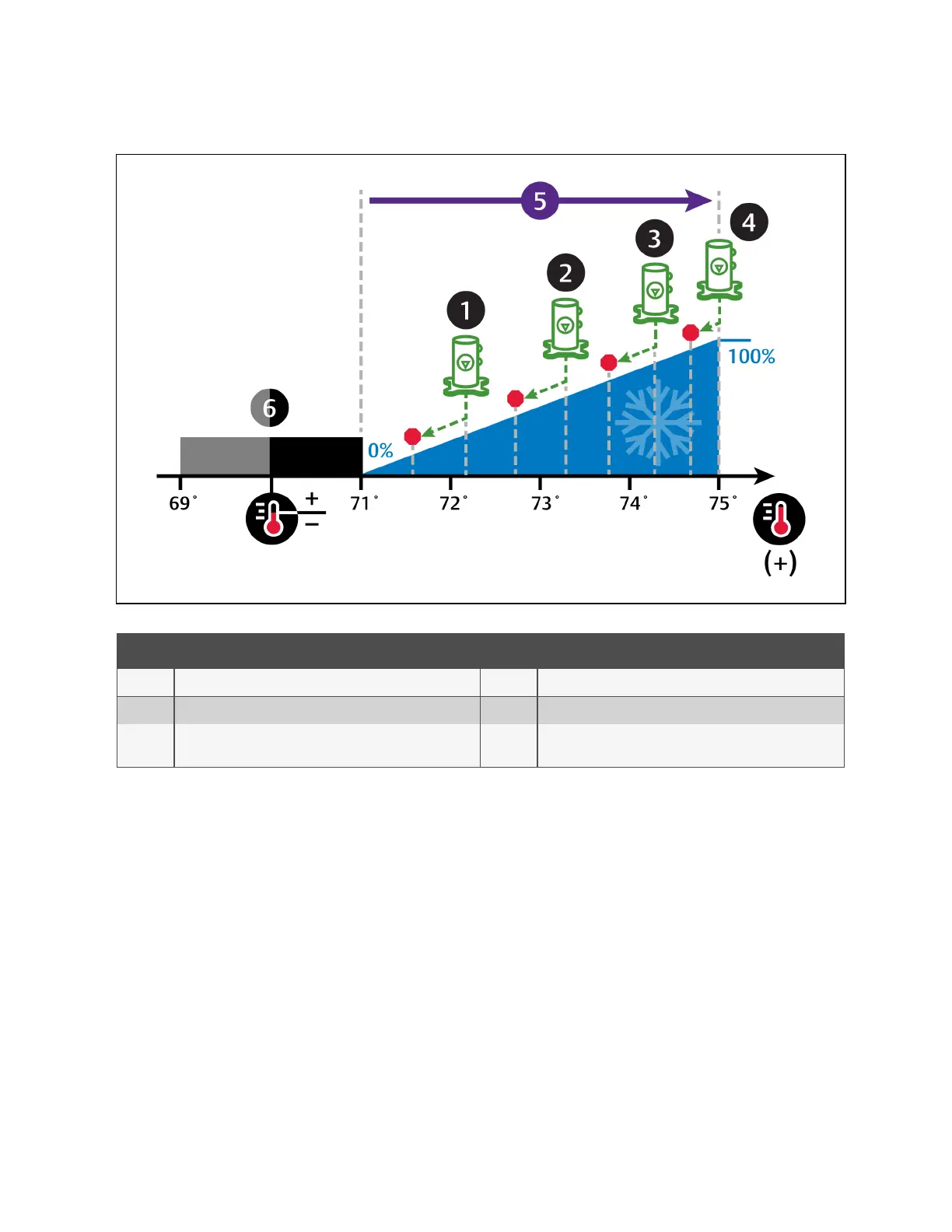
Figure 3.6 Compressor Control—Four Step Capacity
No. Description No. Description
1 Step 1: Compressor 1 starts unloaded. 4 Step 4: Compressors 1 and 2 operate loaded.
2 Step 2: Compressor 2 starts unloaded. 5 ½ of proportional band.
3
Step 3: Compressor 1 operates loaded andcompressor 2
operates unloaded.
6 Deadband.
Digital Scroll Compressors
Digital scroll compressors use time loaded/unloaded to modulate cooling capacity between 10% and 100% to control cooling
more precisely than non-digital compressors. Capacity modulation is achieved by opening and closing a digital solenoid valve
in 15 second intervals while the compressor runs continuously when the cooling requirement is 10% to 100%.
• When the valve is opened (energized, the compressor is unloaded and capacity is 0% (because the scroll plates
are separated so that there is no refrigerant flowing through the compressor).
• When the valve is closed (de-energized), the compressor is loaded and capacity is 100%.
• Capacity is determined by the amount of time that the valve is closed in the 15 second interval. Figure 3.7 on the
next page illustrates solenoid-valve operation when cooling requirement is 66%.
• The valve is closed for 10 seconds (100% cooling).
• The valve is then open for 5 seconds (0% cooling).
• This results in 66% cooling. Essentially, the compressor is partially loaded.
3 Service Operation
33
Vertiv™ Liebert® iCOM™Installer/User Guide