Vertiv | Liebert PEX+ Chilled Water | User Manual 43
Electrical Installation
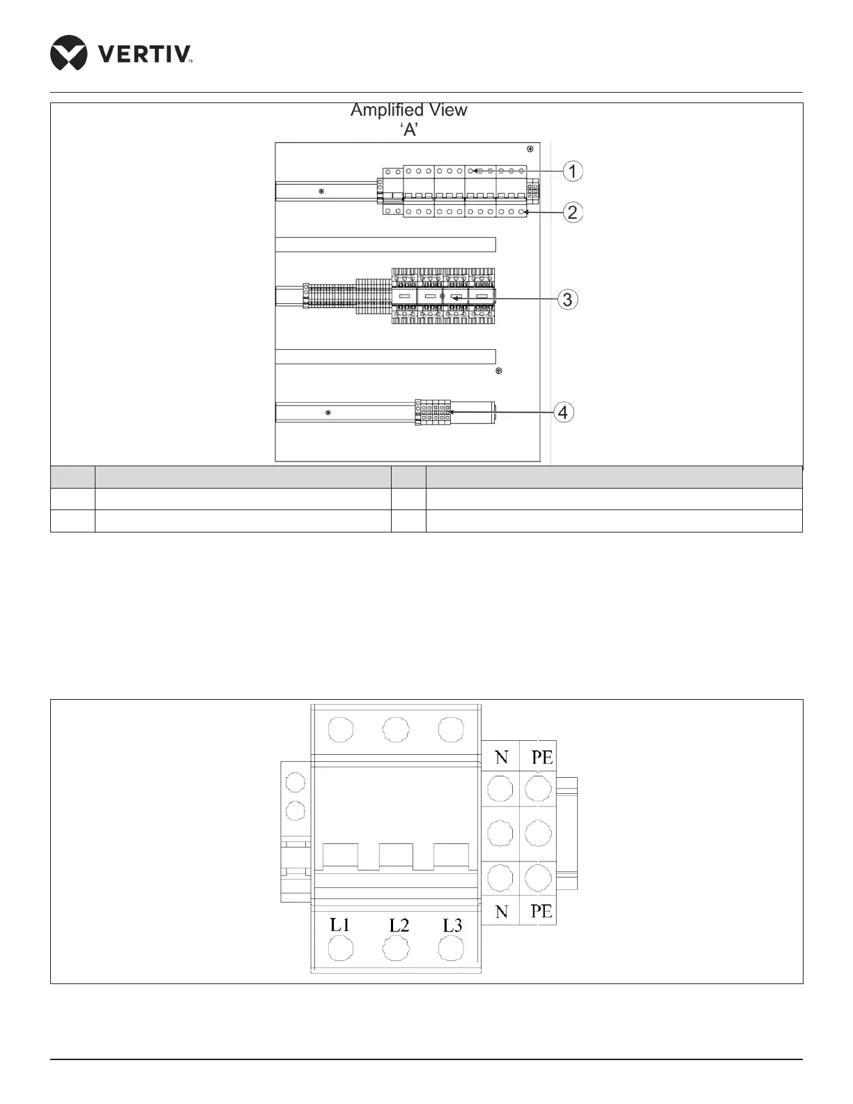
No. Description No. Description
1 MCB 3 Connector and terminal block
2 Cable connector 4 Terminal block
Figure 3-3 Electrical Control Box of P2070DC
• Connecting Power Cable of Indoor Unit
Figure 3-4 shows the details of power connectors in electrical control box, connects terminals L1 ~ L3, N, and PE respec-
tively to 3-phase external power supply. Reserve some redundancy of the incoming cable and fix the cable to the cable
clamp located on the inner side panel of the unit, refer Figure 3-3. For cable specification and the rated Full Load Ampere
(FLA) in the Table 3-1.
Figure 3-4 Enlarge View of Power Connector