Vertiv | Liebert PEX+ Chilled Water | User Manual 45
Electrical Installation
• Connecting Control Cables
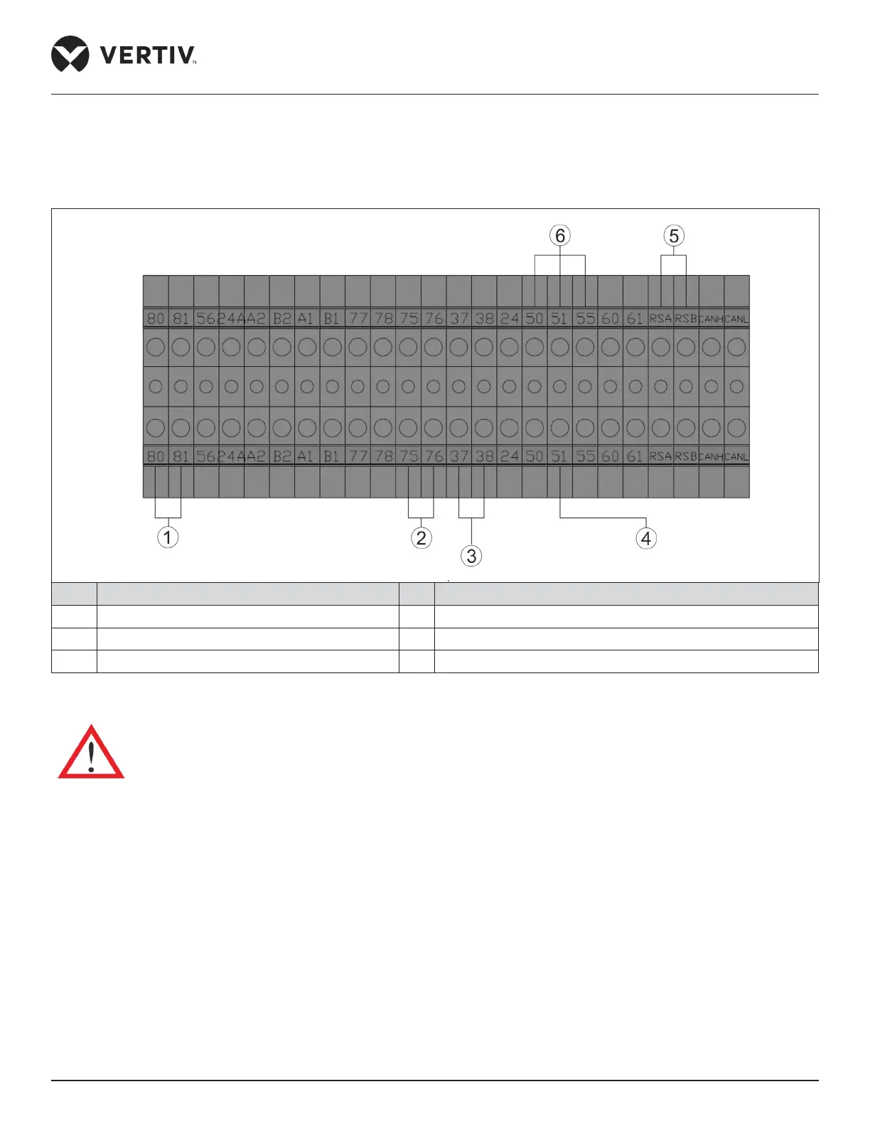
The position of field connection terminals is shown in Figure 3-1.and Figure 3-2 for upflow and downflow units
respectively, and the amplified view is shown in Figure 3-5. The upper part of the terminal block is connected to the
unit, while the lower part serves as user control signal interfaces.
No. Description No. Description
1 External alarm output of the smoke sensor 4 Water leakage alarm terminal
2 Connecting common alarm terminal 5 R485 port
3 37/38 shorted remove upon remote shutdown 6 Customized alarm terminal 24 is the common terminal
Figure 3-5 Enlarged View of Terminal Block
Anti-static measures should be taken before connecting the control cables.
• Connecting Water Under Floor Sensor
Each unit is equipped with a water under floor sensor. Connect one end of the sensor to Terminal 51# and the other
end to the common Terminal 24#.
The number of the sensors in parallel connection can be connected, but each unit has only one water under floor
alarm.
• Remote Shutdown
As shown in Figure 3-5, 37# and 38# terminals can connect to remote shutdown switch, which has been shorted in
the factory and the shorting cable should be removed if the terminals are to be connected to the remote shutdown
switch.