Vertiv™ | Liebert® SRC-G | User Manual
13
Mechanical Installation
2.3. System Installation Arrangement
2.3.1. System Arrangement during Installation
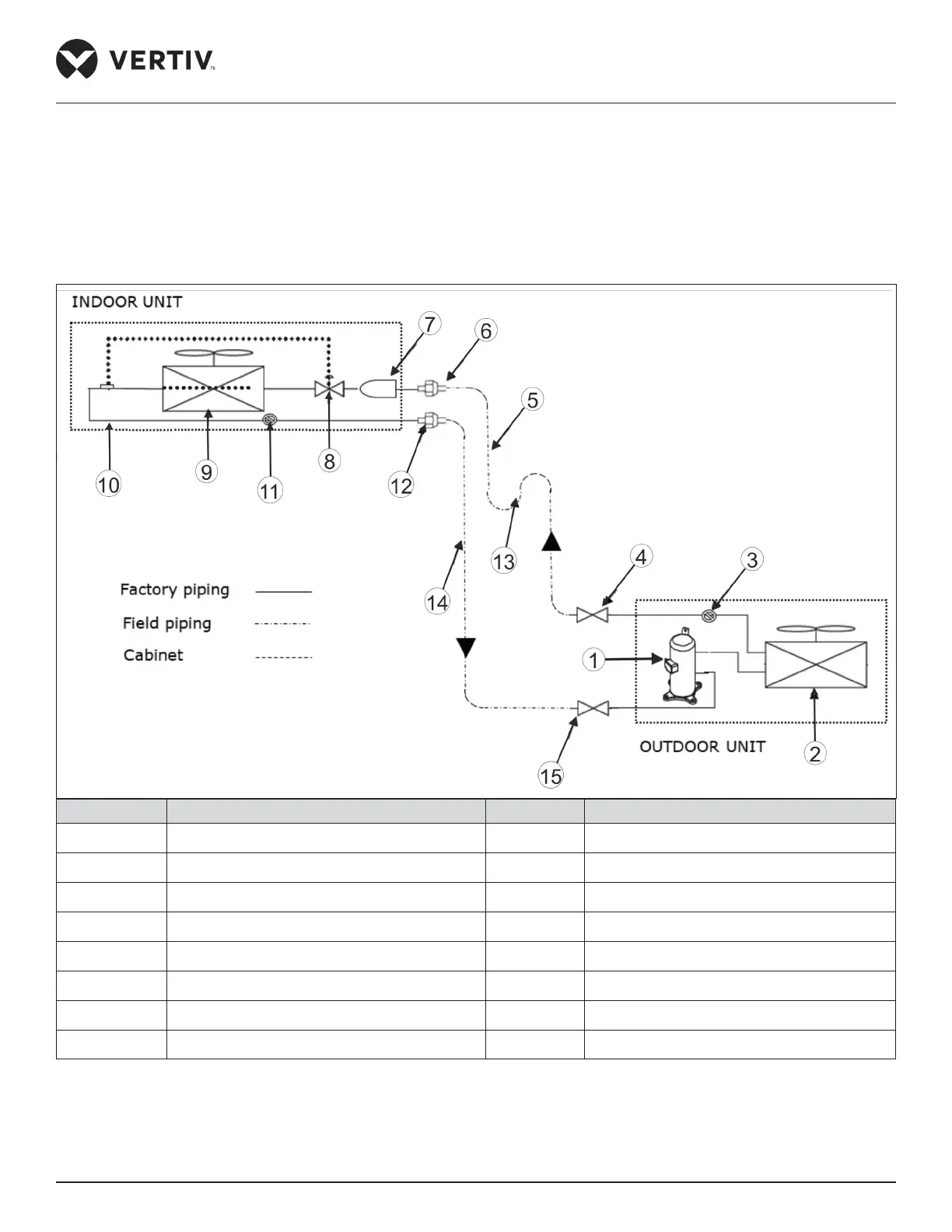
The refrigerant piping is required to connect the indoor and the outdoor units of the air-cooled system.
The system arrangement diagram of the refrigeration system is shown in Figure 2-2.
No. Description No. Description
1 Compressor 9 Evaporator coil
2 Condenser coil 10 TXV bulb
3 Liquid line Schrader valve 11 Gas (suction) line Schrader valve
4 Liquid line Service valve 12 Gas line flared connection
5 Liquid line 13 Trap (as per piping details)
6 Liquid line flared connection 14 Gas line
7 Filter & drier 15 Gas line service valve
8 Expansion valve
Figure 2-2 System Arrangement Diagram