Vertiv™ | Liebert® SRC-G | User Manual 35
Electrical Installation
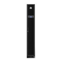
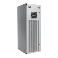
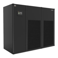
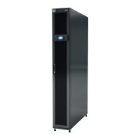
Table 3-2 Required Cables from Customer End
Cable SRC03GES SRC07GES SRC07GET SRC11GET
Incoming power cable
3C x 4 mm
2
(L + N + PE)
5C x 4 mm
2
(3L + N + PE)
Customer in 1 2C x 0.5 mm
2
Customer in 2 2C x 0.5 mm
2
Remote shut 2C x 0.5 mm
2
Fire alarm 2C x 0.5 mm
2
Common alarm 2C x 0.5 mm
2
Sequencing high 2C x 0.5 mm
2
Sequencing low 2C x 0.5 mm
2
Communication LAN cable with male connector
3.2. Installation Notes
All power and control cabling and ground connections must be in accordance with the respective national
and local electrical regulations. The power cables should not be lighter than the ordinary PVC sheathed cord
GB5023.1 (idt IEC60277) line 53.
1. The connections of all the power cables, control cables, and ground cables should be in compliance with the
respective local and national electrical regulations.
2. Observe the unit name-plate for the full load current. The cables sizes must meet the conditions as specified
in the respective local cabling protocols and rules.
3. If the power cable connection is damaged, it has to be replaced immediately to eliminate the danger. The
replacement procedure must be carried out by an authorized professional or experienced service personnel.
4. The electrical installation and maintenance must be carried out by some authorized personnel or a trained
engineer well-versed with the inner workings of the electrical connection (for example, a service engineer
from the manufacturer’s side).
5. Prior to the cabling, a voltmeter must be used to measure the power supply voltage and ensure that the power
supply has been switched O.
6. The front end of the unit needs to be equipped with a power-disconnection device to ensure safe operation.
7. Use screws, guide rails, or other modes to fix the device firmly during the installation process to avoid
movement or shaking during the start-up or operation mode.

 Loading...

