Vertiv™ | Liebert® SRC-G | User Manual 36
Electrical Installation
3.3. Indoor Unit Connection
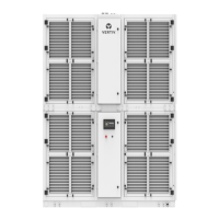
No. Description
1 Indoor terminal cover plate
Figure 3-1 Indoor Cable Terminal Location
Refer the following procedure to connect the power supply cables and control cable of unit:
1. Refer Table 3-1 for indoor power cable and fan control cable
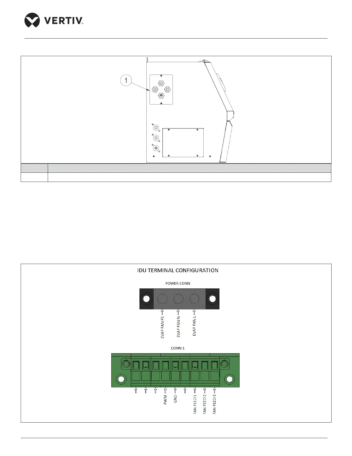
2. Open the cover plate and access barrier terminal block (multi-pin connector).
3. Route the power cable through the cover plate wire hole and connect it to the barrier terminal lock, refer
Figure 3-2 for terminal connection.
Figure 3-2 Control Field Connection Terminals for Single Phase