Vertiv™ | Liebert® SRC-G | User Manual
14
Mechanical Installation
2.3.2. System Installation Mode
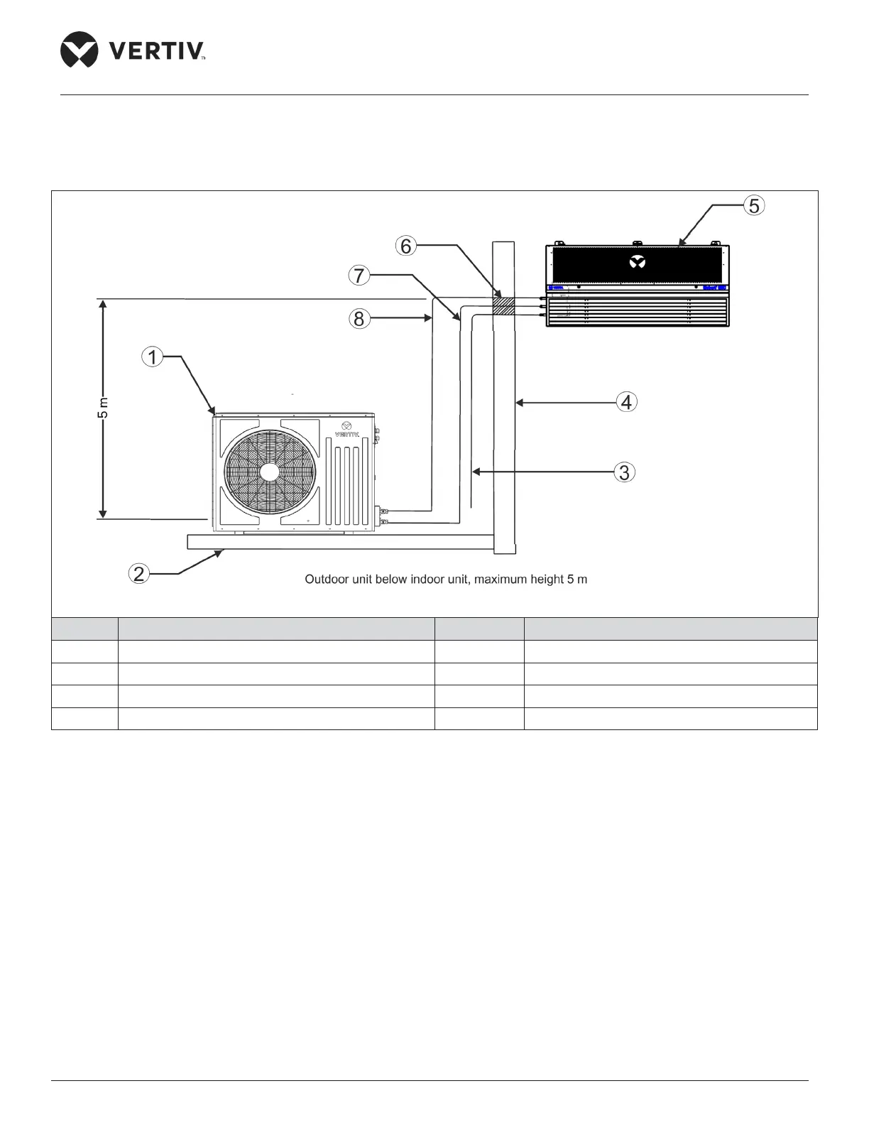
The system installation schematic diagram explains the process of installation of the outdoor unit.
No. Description No. Description
1 Outdoor Unit 5 Indoor Unit
2 Mounting floor 6 Seal for pipe protection through wall
3 Condensate drain pipe 7 Liquid line
4 Wall 8 Gas line (1:100)
Figure 2-3 Indoor Unit is Placed Higher than Outdoor Unit during Installation