Vertiv™ | Liebert® SRC-G | User Manual
15
Mechanical Installation
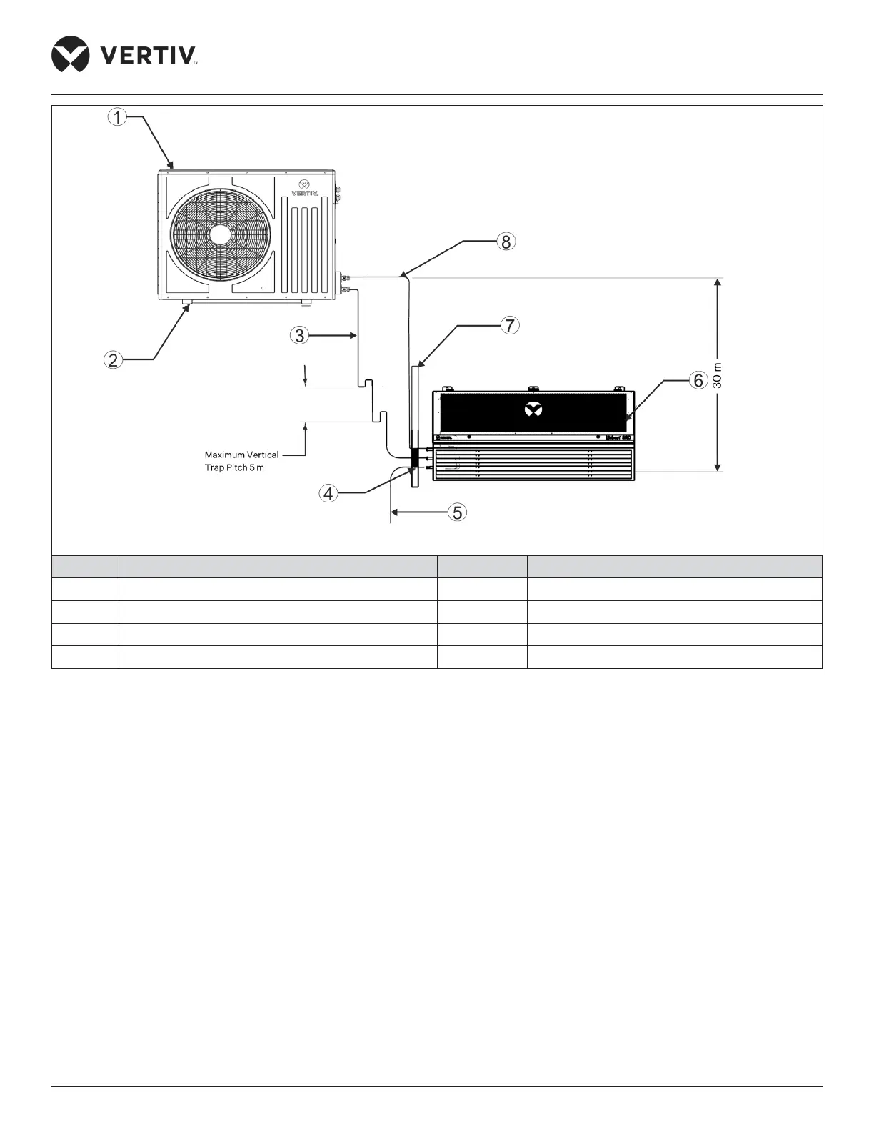
No. Description No. Description
1 Outdoor unit 5 Condensate drain pipe
2 Stand/Platform/Raised Platform 6 Indoor Unit
3 Liquid (Discharge) line 7 Wall
4 Seal for pipe protection through wall 8 Gas (Suction) line (1:100)
Figure 2-4 Indoor Unit is Placed Lower than Outdoor Unit during Installation
The illustration in Figure 2-3 depicts the schematic diagram of system installation when the indoor unit is
installed at a higher level than the outdoor unit. The maximum height dierence allowed in this case is 5 m. When
the indoor unit is installed at a lower level than the outdoor unit, maximum allowed height dierence is 30 m
(refer Figure 2-4). Maximum allowed equivalent piping length is 60 m.