9.3 Routing pipework
During the design phase, ensure the pipes are installed with a fall
from the collector. This ensures better steam expulsion characteris-
tics in the solar thermal system as a whole in the event of stagna-
tion. The thermal load exerted on all system components is reduced
(see page 133).
9.4 Equipotential bonding/lightning protection of the solar thermal system
Connect the solar circuit pipework with an electrical conductor in the
lower part of the building in accordance with VDE [or local] regula-
tions. The integration of the collector system into a new or existing
lightning protection facility or the provision of local equipotential
bonding must only be carried out by authorised personnel. Local
conditions must be taken into consideration.
9.5 Thermal insulation
The thermal insulation material provided must withstand the operat-
ing temperatures to be expected and must be permanently protected
against the influence of moisture. Some open pore insulation mate-
rial that can be subjected to high thermal loads cannot provide relia-
ble protection against moisture produced by condensation. The high
temperature versions of close-cell insulating hoses offer adequate
protection against moisture, but have a maximum loading tempera-
ture of approx. 170 °C. However, the connections at the collector can
be subjected to temperatures up to 200 °C (Vitosol-F flat-plate col-
lector). In switching collectors (Vitosol-FM/-TM), the maximum ach-
ievable temperature in the collector area is approx. 145 °C to 170
°C.
The thermal insulation of the solar lines routed outdoors must be
protected against pecking damage from birds and gnawing by small
animals, as well as against UV radiation. A cover (e.g. metal sheath)
protecting the insulation against damage by small animals also pro-
vides UV protection.
9.6 Solar lines
■ Use stainless steel pipe or commercially available copper pipe and
bronze fittings.
■ Metal seals (conical or locking rings and compression fittings) are
suitable for solar lines. Should alternative seals be used, such as
flat gaskets, their manufacturer must give an assurance of their
adequate resistance to glycol, pressure and temperature.
In case of connections with hemp seals, use a pressure and tem-
perature-resistant sealant. Use hemp connections as little as pos-
sible due to their comparatively high air permeability and never in
the immediate vicinity of collectors.
■ Generally, copper lines in solar circuits are brazed or joined by
press fittings. Soft solder could be weakened, particularly near the
collectors, due to the maximum temperatures that may occur
there. Metal sealing connections, locking ring fittings or Viessmann
push-fit connections with double O-rings are the most suitable.
Note
If using press fittings, ensure the seal rings are suitable (resistant
to glycol and temperature). Only use seal rings that have been
approved by the manufacturer.
■ All components to be used must be resistant to the heat transfer
medium.
Note
Fill solar thermal systems only with Viessmann "Tyfocor LS" heat
transfer medium.
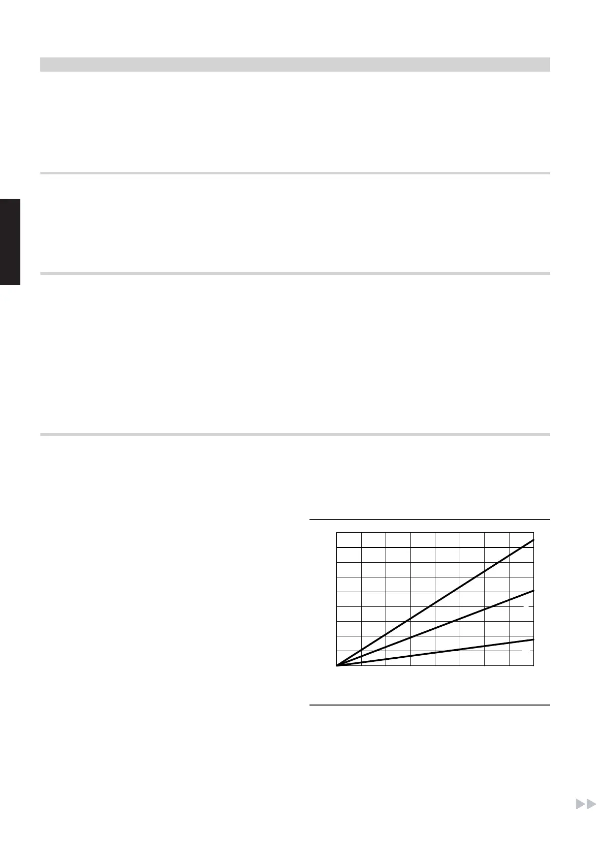
■ Take high temperature differentials in the solar circuit into consid-
eration when routing and securing pipes.
At pipe sections that may be subject to steam loads, temperature
differentials of up to 200 K can be expected; otherwise 120 K can
be expected.
Temperature differential in K
0 50 100 150 200
0
2
4
6
8
10
12
14
16
18
Longitudinal expansion in mm
A
B
C
A
5 m pipe length
B
3 m pipe length
C
1 m pipe length
■ Route the solar connection lines through a suitable roof outlet
(ventilation tile).
For suitable accessories for the solar connection line roof outlet,
see page 95.
Design information regarding installation
(cont.)
96
VIESMANN
VITOSOL
9
5822 440 GB