G 85 Technical Data
wc_td000214gb.fm 117
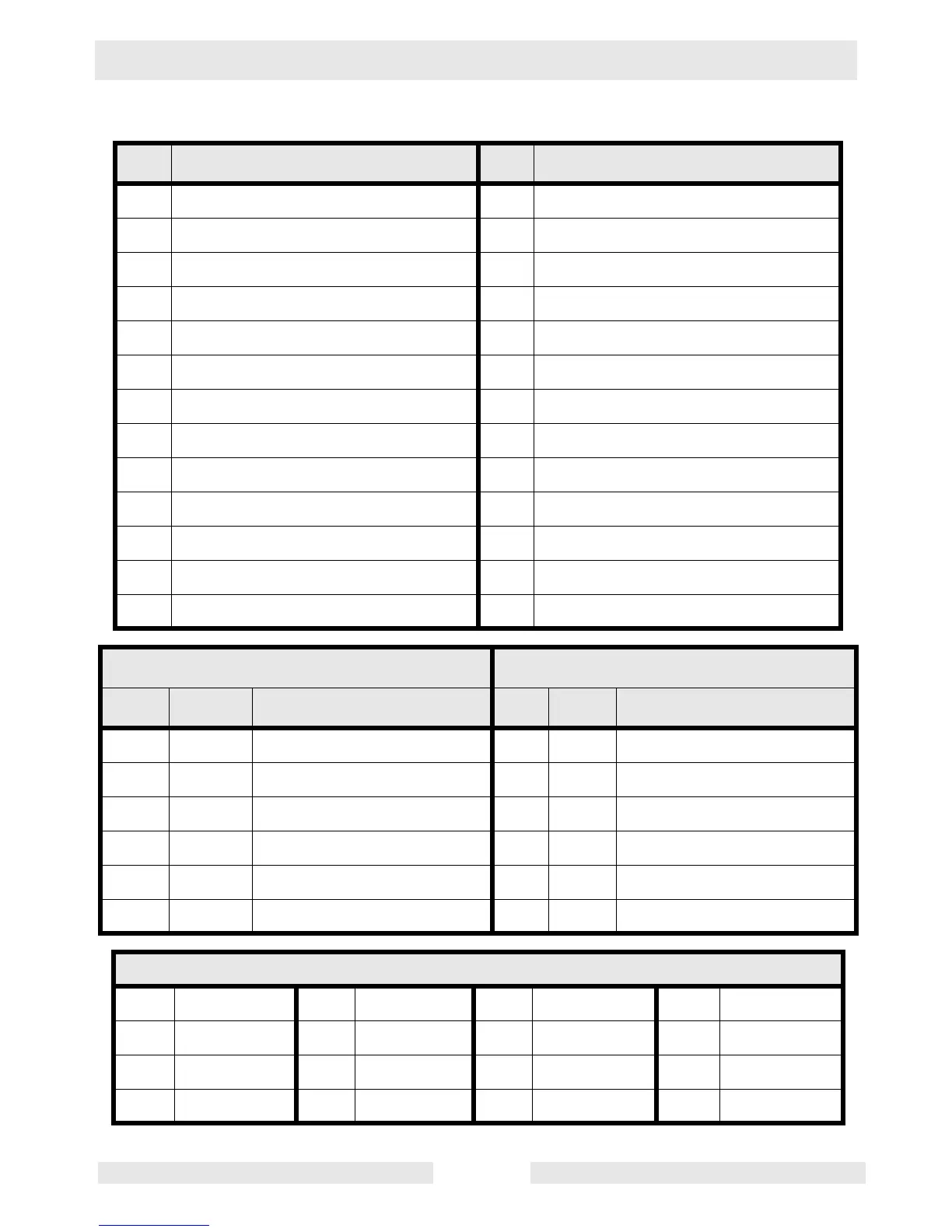
Engine Wiring Components—John Deere with ECU
Ref. Description Ref. Description
1 Plug 1 — engine sender inputs 14 Battery
2 Plug 2 — engine start/run outputs 15 ECM 10A fuse
3 Main circuit breaker (3-phase lugs) 16 Starter relay
4 Shunt trip coil 17 Starter
5 Emergency stop switch 18 Alternator
6 Engine Control Module (ECM) 19 B+ terminal block
7 Safety interlock switch 20 System 10A fuse
8 Remote start terminals 21 System 30A fuse
9 Fuel level sender 22 Harness connector
10 Intake heater 23 CAN bus connector
11 Slave preheat relay 24 Diagnostic connector
12 Mechanical lugs (3 phase) 25 ECU harness connector
13 Start switch 26 Hour meter switch
ECM Plug 1 Wires ECM Plug 2 Wires
Pin Wire Description Pin Wire Description
10 Gr/61 Emergency stop 5 R/18 Battery + (for relays)
3 W/L/56 Oil pressure sender 1 Y/63 Crank (12V output)
9 Or/60 Remote start 2 V/64 Run/Fuel (12V output)
12 W/V/62 Fuel level 3 73 Remote annunciator (NA)
8 B/59 Battery – 4 75 Remote annunciator (NA)
7 R/53 Battery + (for ECM board) - - ---
Wire Colors
B Black R Red Y Yellow Or Orange
G Green T Tan Br Brown Pr Purple
L Blue V Violet Cl Clear Sh Shield
P Pink W White Gr Gray LL Light blue
 Loading...