Mobile Generator Output Voltage Troubleshooting
wc_tx000726gb.fm 81
8.13 Checking the Exciter Rotor Winding
Prerequisites Generator shut down
Procedure Follow the procedure below to check the exciter rotor winding.
1. Remove the rear baffle from the machine.
2. Remove the cover from the generator.
3. Remove the screws that secure the bearing carrier to the stator.
4. Disconnect the blue and yellow wires from the AVR.
5. Using a puller, pull the bearing carrier/exciter stator from the stator housing.
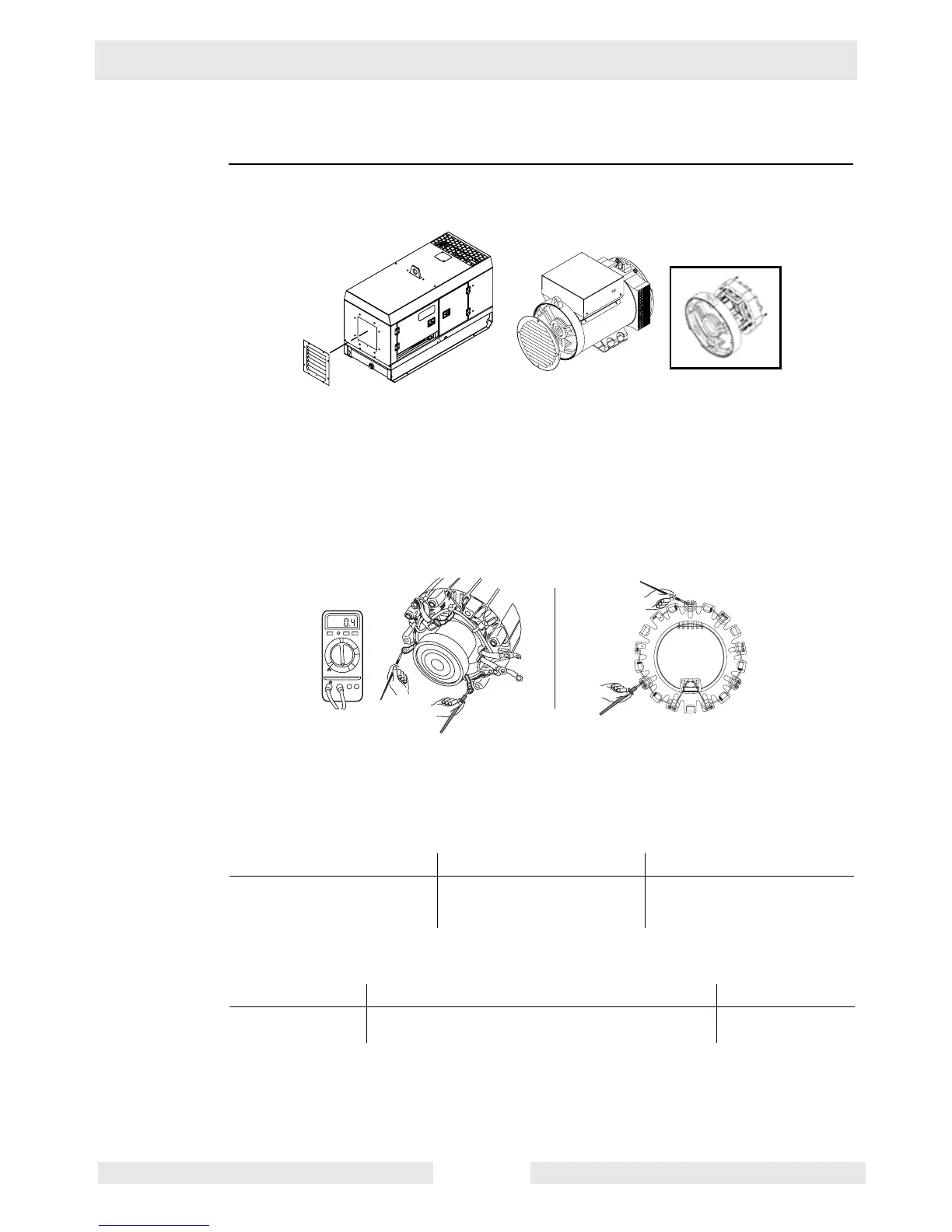
6. On older machines, remove the exciter rotor leads from the diode plates. The three
exciter rotor leads are connected to the diode plates in between each pair of diodes. Or,
remove the diode plates completely to access the exciter rotor leads.
7. On newer machines, the location of the three exciter rotor leads is also in between each
pair of diodes.
8. Measure the resistance across each lead and the other two leads (one lead at a time).
Is 0.3–1.0 Ohms measured in each case?
9. Check each lead for short (path) to the rotor shaft.
Does each lead measure “OPEN” or “OL” to the rotor shaft?
10.Reassemble the generator components.
The exciter rotor winding has now been checked. Continue with Checking Stator Windings
at the Voltage Selector Switch.
Yes____ No____ Your readings
The exciter rotor windings
are OK.
The exciter rotor has failed.
Call Wacker Neuson
Service.
_____; _____; _____
Yes____ No____ Your reading
The main rotor
winding is OK.
The main rotor winding has failed.
Call Wacker Neuson Service.
wc_gr003811
wc_gr003709
1000
200
20
2
200m
F
V
A
V- COM
Old New
 Loading...