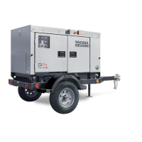
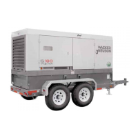
ECM Background Information Mobile Generator
40 wc_tx000713gb.fm
4.9 Control Wiring Numbering & Colors
See Graphic: wc_gr002924
Generator and control wires are marked and color coded to assist in
tracing line connections and troubleshooting. The charts below list wire
labels and colors followed by a description of their use.
G 25 Control Module
Plug 1: Engine Sender Inputs (12-pin connector)
1 Black Magnetic pickup
2 Clear, shield Magnetic pickup
3 White/Blue Oil pressure sender
5 Yellow Water temperature sender
7 Red Run/Off/Auto switch, +12V (positive)
8 Black 12VDC supply, - ground (negative)
10 Orange Remote start contacts
11 Red Emergency stop pushbutton
12 White-Violet Fuel level sender
Plug 2: Engine Start Inputs/Outputs (8-pin connector)
1 Yellow-Red Out; 12VDC to starter relay
2 Violet Out; 12VDC to E-stop switch
5 Red In; 12VDC from B+ through 10A fuse
7 Red In; 12VDC from B+
8 Green Out; 12VDC to glow plug relay
Plug 3: Current Transformer Inputs (6-pin connector)
1 White Ammeter line input CT common
2 Brown Ammeter line input CT1
4 Orange Ammeter line input CT3
5 Yellow Ammeter line input CT2
Plug 4: Line Voltage Inputs (4-pin connector)
2 Brown Voltage line input L1 at volt selector #3

 Loading...
