Mobile Generator Theory of Operation
wc_tx001077gb.fm 15
2 Theory of Operation
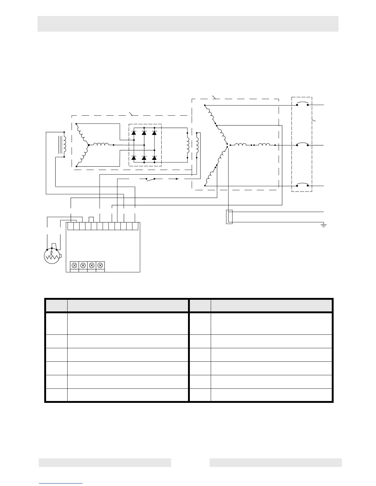
2.1 Basic Schematic
Ref. Component Ref. Component
a Exciter stator winding g Automatic Voltage Regulator
(AVR)
b Rotor assembly h Main circuit breaker
c Exciter rotor winding i Auxiliary winding
d Rotating rectifier (diodes) j Voltage adjusting rheostat
e Main rotor winding k Lug door switch
f Main stator windings l Stator assembly
VOLT
T1
T5
T9
T2
N
T7
T10
T3
T6
T11
T4
T8
T12
L1
L2
L3
wc_gr003643
3-Phase AC out
3-Phase
AC output
DC out (exciter field)
AC sensing
AC in
DC in
LY
+
+
–
–
a
c
d
b
e
f
l
h
g
j
i
k
BRGYL
BW
GND
L/W LR
5C
AMP HZ STAB
5B 7 5A 6 5 4A 4 3A 3 2 1
n/a n/a
 Loading...