Mobile Generator Output Voltage Troubleshooting
wc_tx000726gb.fm 75
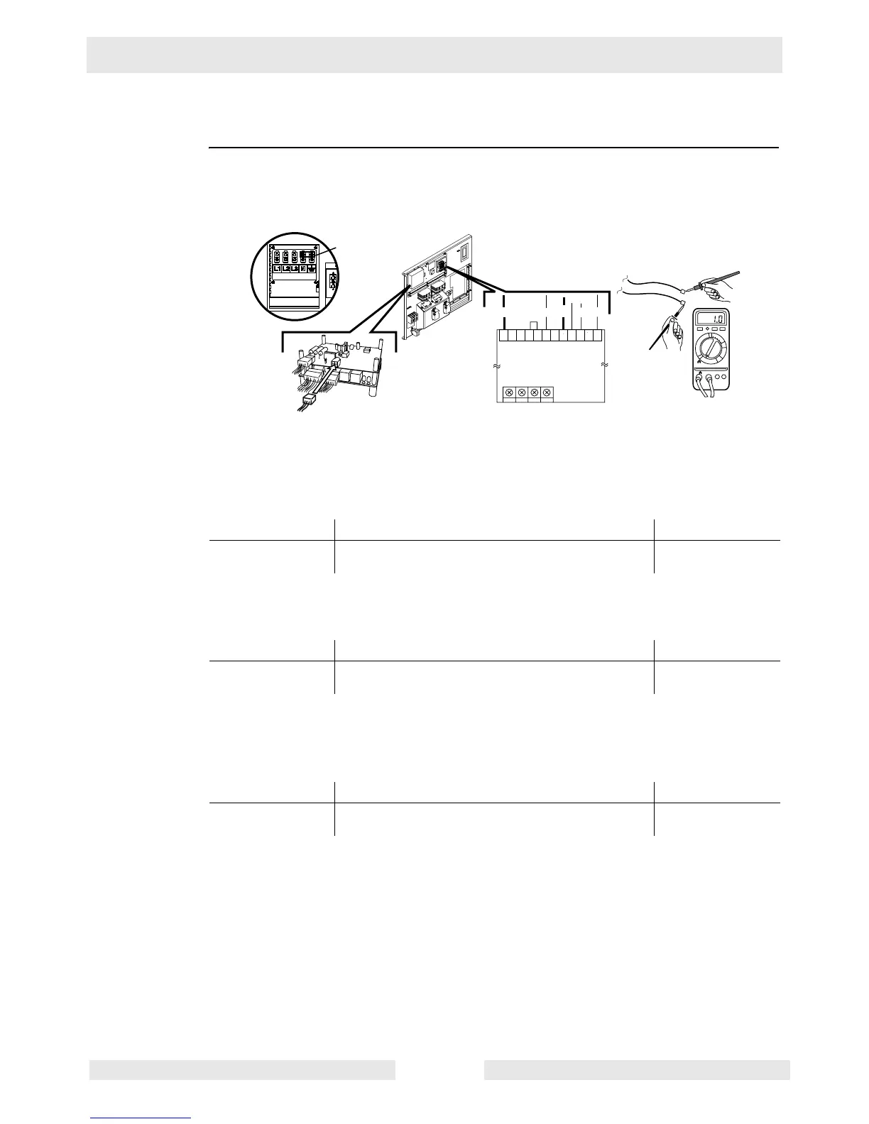
8.7 Checking the AVR Sensing Wires
Prerequisites Generator shut down
Procedure Follow the procedure below to check the AVR sensing wires.
1. Open the large hinged panel and locate the Engine Control Module (ECM) and the Auto-
matic Voltage Regulator (AVR).
2. Disconnect the 4-pin connector (it has 3 wires) from the ECM.
3. Remove the green and black wires from the AVR.
4. Measure the resistance across the green and black wires.
Is 0.2–1.0 Ohms measured?
5. Measure the resistance between the green wire and the ground lug. Also check
between the black wire and the ground lug.
Is 0.2–1.0 Ohms measured?
6. Remove the bus bar between the neutral lug and the ground lug.
7. Measure the continuity between the green wire and the ground lug. Also check between
the black wire and the ground lug.
Does each wire measure “OPEN” or “OL” to the ground lug?
8. Reconnect the 4-pin connector and the green and black wires to the AVR.
NOTICE: NEVER run the generator when the green and black wires are disconnec-
ted from the AVR and all other wires are connected to the AVR. Damage to the gen-
erator will occur.
9. Reconnect the bus bar. DO NOT run the generator with the bus bar disconnected.
The AVR sensing wires have now been checked. Continue with Flashing the Generator.
Yes____ No____ Your reading
Continue Remove the vent cover from the generator and
check the generator for damage.
Yes____ No____ Your reading
Continue Remove the vent cover from the generator and
check the generator for damage.
Yes____ No____ Your reading
The sensing wires
are OK.
Remove the vent cover from the generator and
check the generator for damage.
ECM
Bus bar
L/W
wc_gr003694
VOLT
B
R
G
Y L
5C
AMP HZ STAB
5B 7 5A 6 5 4A 4 3A 3 2 1
n/a
n/a
AVR
Green (G)
Black (B)
1000
200
20
2
200m
F
V
A
V- COM
 Loading...