Output Voltage Troubleshooting Mobile Generator
wc_tx000726gb.fm 82
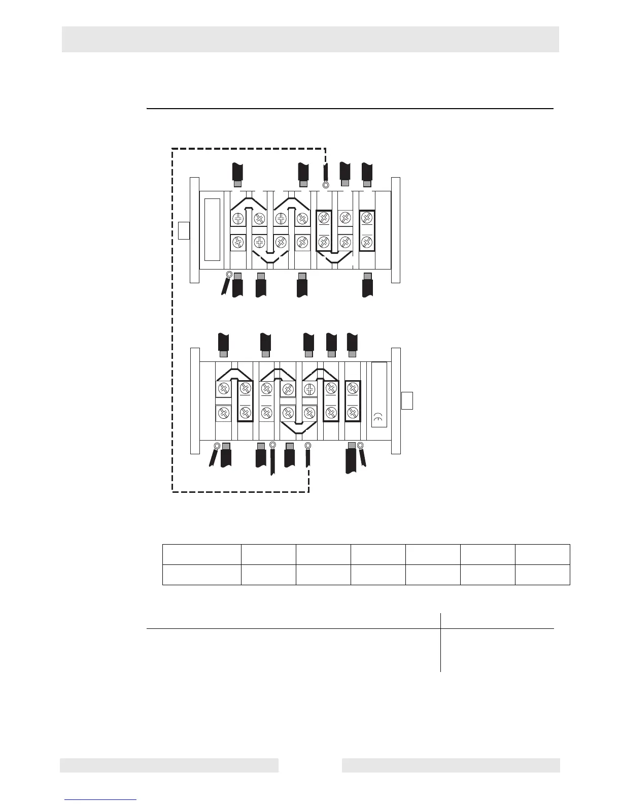
8.14 Checking Stator Windings at the Voltage Selector Switch
Prerequisites Generator shut down
Procedure 1. Follow the procedure below to check the main stator windings at the generator.
2. Remove the cover from the Voltage Selector Switch (VSS).
3. Note the positions and labels of all wires connected to the VSS (T2, T3, T4 etc.).
4. Check the resistance across each pair of wires for each winding (T1–T2, T3–T4, and so
on up to T11–T12). Note: T1, T4, T8, and T9 are located at the terminal strip.
Do all six stator windings measure approximately 0.2 Ohms?
5. Reconnect the wires and reinstall the generator components.
The main stator windings have now been checked.
wc_gr003928
T2 T6
T11
L0
N
L1
T12 L2
1 5 9 13 17 21 25
3
Br
7 11 15 19 23 27
26 22 18 14 10 6 2
28 24 20 16 12 8 4
L3 L2
T10
T7
N
T3
Or
ECM
ECM
ECM
TB*
TB**
TB
TSTSGen Gen
Gen
CB
Gen TS TSLug
CB TS
T5
Gen
Gen
Y
N
AVR = to Automatic Voltage Regulator
ECM = to Engine Control Module
Gen = from generator
TB* = to terminal block R1 (T7 on older)
TB**= to terminal block R2 (T9 on older)
TS = to terminal strip
CB = to main circuit breaker
AVR
G
T1–T2 T3–T4 T5–T6 T7–T8 T9–T10 T11–T12
Your readings
Yes____ No____
The main stator windings are OK. If there is a
difference between the readings taken here and those taken at
the lugs, the VSS has failed; replace it.
The main stator win-
dings have failed. Call
Wacker Neuson
Service.
 Loading...