Output Voltage Troubleshooting Mobile Generator
wc_tx000726gb.fm 74
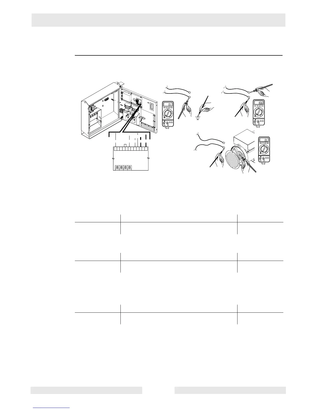
8.6 Checking the Exciter Stator
Prerequisites Generator shut down
Procedure Follow the procedure below to check the exciter stator.
1. Open the large hinged panel and locate the Automatic Voltage Regulator (AVR).
2. Disconnect the blue and yellow wires from the AVR.
3. Measure the continuity between the blue wire and ground. Also measure between the
yellow wire and ground.
Does each wire measure “OPEN” or “OL” to ground?
4. Measure the resistance across the blue and the yellow wires.
Is 10.6–12.0 Ohms measured?
5. Remove the vent cover from the generator to expose the rotor.
6. Measure the continuity between the blue wire and the rotor. Also measure between the
yellow wire and the rotor.
Does each wire measure “OPEN” or “OL” to the rotor?
7. Reconnect the wiring, and re-install the vent cover.
The auxiliary winding has now been checked. Continue with Checking the AVR Sensing
Wires.
Yes____ No____ Your reading
Continue Remove the vent cover from the generator and
check the generator for damage.
Yes____ No____ Your reading
Continue Remove the vent cover from the generator and
check the generator for damage; then continue.
Yes____ No____ Your reading
The excitor stator
is OK.
The exciter stator has failed.
Call Wacker Neuson Service.
wc_gr003693
L/W
VOLT
B
R
G
Y L
5C
AMP HZ STAB
5B 7 5A 6 5 4A 4 3A 3 2 1
n/a
n/a
AVR
Blue (L)
Yellow (Y)
Blue (L)
Yellow (Y)
Blue (L)
Yellow (Y)
1000
200
20
2
200m
F
V
A
V- COM
1000
200
20
2
200m
F
V
A
V- COM
1000
200
20
2
200m
F
V
A
V- COM
 Loading...